Toyota Camry (XV70): Components
COMPONENTS
ILLUSTRATION
.png)
|
*A | for 2WD |
*B | for RH Side |
|
*C | for LH Side |
- | - |
|
*1 | NO. 1 FLOOR UNDER COVER |
*2 | NO. 2 FLOOR UNDER COVER |
.png) |
N*m (kgf*cm, ft.*lbf): Specified torque |
- | - |
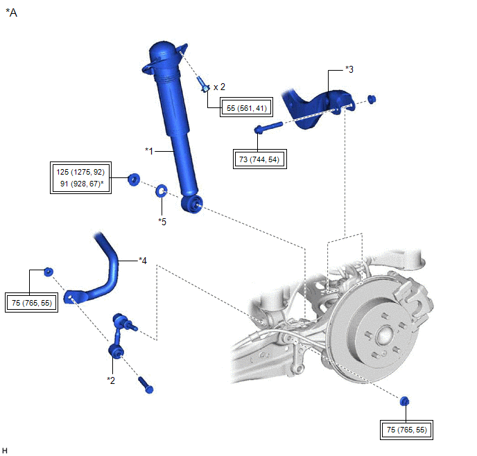
ILLUSTRATION
|
*A | for 2WD |
- | - |
|
*1 | REAR SHOCK ABSORBER ASSEMBLY |
*2 | REAR STABILIZER LINK ASSEMBLY |
|
*3 | REAR UPPER CONTROL ARM ASSEMBLY |
*4 | REAR STABILIZER BAR |
|
*5 | PLATE WASHER |
- | - |
.png) |
Tightening torque for "Major areas involving basic vehicle performance such as moving/turning/stopping": N*m (kgf*cm, ft.*lbf) |
* | For use with a ball joint lock nut wrench |
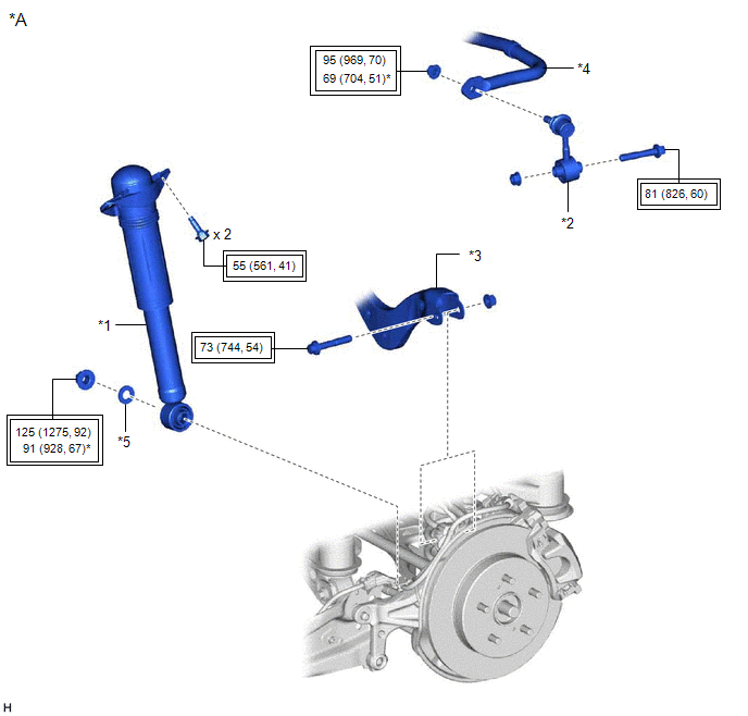
ILLUSTRATION
|
*A | for AWD |
- | - |
|
*1 | REAR SHOCK ABSORBER ASSEMBLY |
*2 | REAR STABILIZER LINK ASSEMBLY |
|
*3 | REAR UPPER CONTROL ARM ASSEMBLY |
*4 | REAR STABILIZER BAR |
|
*5 | PLATE WASHER |
- | - |
|
|
Tightening torque for "Major areas involving basic vehicle performance such as moving/turning/stopping": N*m (kgf*cm, ft.*lbf) |
* | For use with a ball joint lock nut wrench |
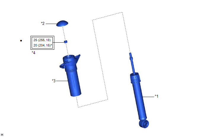
ILLUSTRATION
|
*1 | REAR SHOCK ABSORBER ASSEMBLY |
*2 | REAR SHOCK ABSORBER CAP |
|
*3 | REAR SUSPENSION SUPPORT ASSEMBLY |
*4 | REAR SUPPORT TO REAR SHOCK ABSORBER NUT |
|
|
Tightening torque for "Major areas involving basic vehicle performance such as moving/turning/stopping": N*m (kgf*cm, ft.*lbf) |
* | For use with SST |
|
● | Non-reusable part |
★ | Precoated part |
READ NEXT:
 Removal
REMOVAL CAUTION / NOTICE / HINT
The necessary procedures (adjustment, calibration, initialization, or registration) that must be performed after parts are removed and installed, or replaced during r
Inspection
INSPECTION PROCEDURE 1. INSPECT REAR SHOCK ABSORBER ASSEMBLY
(a) Compress and extend the rear shock absorber assembly rod 4 or more times.
Standard: When compressed and extended at a constant spe
Installation
INSTALLATION CAUTION / NOTICE / HINT
HINT:
Use the same procedure for the RH side and LH side.
The following procedure is for the LH side.
PROCEDURE 1. INSTALL REAR SUSPENSION SUPPORT AS
SEE MORE:
Diagnostic Trouble Code Chart
DIAGNOSTIC TROUBLE CODE CHART Wiper and Washer System
DTC No. Detection Item
DTC Output from Link
B1245 Lost Communication with Wiper ECU LIN
Main Body
B1370 ECU Malfunction
Wiper
B1372 Wiper Switch Signal Mismatch b
Rear Turn Signal Light Bulb
ReplacementREPLACEMENT CAUTION / NOTICE / HINT
HINT:
Use the same procedure for the RH side and LH side.
The following procedure is for the LH side.
PROCEDURE 1. REMOVE REAR COMBINATION LIGHT COVER
Click here 2. SEPARATE REAR COMBINATION LIGHT ASSEMBLY
Click here 3. REMO
