Toyota Camry (XV70): Removal
REMOVAL
CAUTION / NOTICE / HINT
The necessary procedures (adjustment, calibration, initialization, or registration) that must be performed after parts are removed and installed, or replaced during rear shock absorber assembly removal/installation are shown below.
Necessary Procedures After Parts Removed/Installed/Replaced|
Replaced Part or Performed Procedure |
Necessary Procedure | Effect/Inoperative Function when Necessary Procedure not Performed |
Link |
|---|---|---|---|
| Rear wheel alignment adjustment |
|
|
|
|
Suspension, tires, etc. (The vehicle height changes because of suspension or tire replacement) |
Rear television camera assembly optical axis (Back camera position setting) |
Parking assist monitor system |
|
| Panoramic view monitor system |
|
HINT:
- Use the same procedure for the RH side and LH side.
- The following procedure is for the LH side.
PROCEDURE
1. REMOVE REAR WHEEL
Click here
.gif)
2. REMOVE NO. 2 FLOOR UNDER COVER (for 2WD)
(a) for LH Side:
Click here
3. REMOVE NO. 1 FLOOR UNDER COVER (for 2WD)
(a) for RH Side:
Click here
4. LOOSEN REAR SHOCK ABSORBER ASSEMBLY
| (a) Loosen the nut of the rear shock absorber assembly. NOTICE: Hold the rear axle carrier pin while rotating the nut. |
|
5. REMOVE REAR STABILIZER LINK ASSEMBLY
for 2WD: Click here
for AWD: Click here
6. SEPARATE REAR SHOCK ABSORBER ASSEMBLY
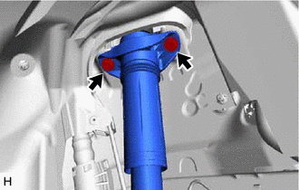
| (a) Remove the 2 bolts and separate the rear shock absorber assembly from the vehicle. |
|
7. SEPARATE REAR UPPER CONTROL ARM ASSEMBLY
| (a) Using a jack and a wooden block, support the rear No. 2 suspension arm assembly. NOTICE:
|
|
.png)
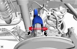
| (b) Remove the bolt and nut, and separate the rear upper control arm assembly from the rear axle carrier sub-assembly. NOTICE: Because the nut has its own stopper, do not turn the nut. Loosen the bolt with the nut secured. |
|
8. REMOVE REAR SHOCK ABSORBER ASSEMBLY
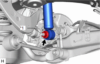
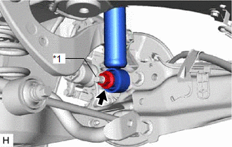
| (a) Remove the nut, plate washer and rear shock absorber assembly from the rear axle carrier sub-assembly. NOTICE: Hold the rear axle carrier pin while rotating the nut. |
|
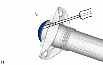
9. REMOVE REAR SHOCK ABSORBER CAP
| (a) Using a screwdriver with its tip wrapped with protective tape, remove the rear shock absorber cap from the rear shock absorber assembly. |
|
10. REMOVE REAR SUSPENSION SUPPORT ASSEMBLY
| (a) Secure the rear shock absorber assembly in a vise using aluminum plates. NOTICE: Do not overtighten the vise. |
|
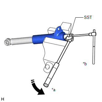
(b) Using SST and a 6 mm hexagon socket wrench, hold the rear shock absorber rod and remove the rear support to rear shock absorber nut.
SST: 09729-97202
(c) Remove the rear suspension support assembly from the rear shock absorber assembly.
READ NEXT:
 Inspection
INSPECTION PROCEDURE 1. INSPECT REAR SHOCK ABSORBER ASSEMBLY
(a) Compress and extend the rear shock absorber assembly rod 4 or more times.
Standard: When compressed and extended at a constant spe
Installation
INSTALLATION CAUTION / NOTICE / HINT
HINT:
Use the same procedure for the RH side and LH side.
The following procedure is for the LH side.
PROCEDURE 1. INSTALL REAR SUSPENSION SUPPORT AS
Disposal
DISPOSAL PROCEDURE 1. DISPOSE OF REAR SHOCK ABSORBER ASSEMBLY
CAUTION:
Always use a cloth to prevent shards of metal flying about due to the release of pressurized gas.
Always wear safety g
SEE MORE:
AHB (Automatic High
Beam)
The Automatic High Beam uses a front camera located behind
the upper portion of the windshield to assess the brightness of
the lights of vehicles ahead, streetlights, etc., and automatically
turns the high beams on or off as necessary.
WARNING
■Limitations of the Automatic High Beam
Do not o
Front Wiper Rubber
ComponentsCOMPONENTS ILLUSTRATION
*1 FRONT WIPER BLADE
*2 WIPER RUBBER
*3 FRONT WIPER RUBBER BACKING PLATE
- - ReplacementREPLACEMENT CAUTION / NOTICE / HINT
NOTICE: Make sure to hold the front wiper arm while lifting it as lifting the front wiper ar
