Toyota Camry (XV70): Front Recognition Camera Heater Malfunction (C1AAE00)
DESCRIPTION
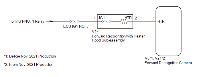
The forward recognition camera controls the flow of current to the forward recognition with heater hood sub-assembly.
If the forward recognition camera detects a malfunction in the forward recognition with heater hood sub-assembly circuit, it will store this DTC.
|
DTC No. | Detection Item |
DTC Detection Condition | Trouble Area |
|---|---|---|---|
|
C1AAE00 | Front Recognition Camera Heater Malfunction | Either of the following conditions is met after 10 seconds have elapsed since the ignition switch was turned to ON:
|
|
WIRING DIAGRAM
CAUTION / NOTICE / HINT
NOTICE:
- Inspect the fuses for circuits related to this system before performing the following procedure.
- When replacing the forward recognition camera, always replace it with a new one. If a forward recognition camera which was installed to another vehicle is used, the information stored in the forward recognition camera will not match the information from the vehicle. As a result, a DTC may be stored.
- When the forward recognition camera is replaced with a new one or the windshield glass is replaced or removed/installed, make sure to read Before Starting Adjustment, then perform optical axis alignment for the forward recognition camera and clear the vehicle control history for each system.
HINT:
Forward recognition camera axis alignment can be performed by using either One Time Recognition, Sequential Recognition or Driving Adjustment.
One Time Recognition: Click here
.gif)
Sequential Recognition: Click here
Driving Adjustment: Click here
PROCEDURE
|
1. | CHECK FOR DTCs |
(a) Clear the DTCs.
Chassis > Front Recognition Camera > Clear DTCs(b) Make sure that the DTC detection conditions are met.
HINT:
If the detection conditions are not met, the system cannot detect the malfunction.
(c) Check for DTCs.
Chassis > Front Recognition Camera > Trouble Codes|
Result | Proceed to |
|---|---|
|
DTC is not output | A |
|
DTC is output | B |
| A |
.gif) | USE SIMULATION METHOD TO CHECK
|
|
.gif)
| 2. |
INSPECT FORWARD RECOGNITION WITH HEATER HOOD SUB-ASSEMBLY |
(a) Turn the ignition switch off.
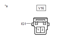
| (b) Disconnect the forward recognition with heater hood sub-assembly connector. |
|
(c) Measure the resistance according to the value(s) in the table below.
Standard Resistance:
|
Tester Connection | Condition |
Specified Condition |
|---|---|---|
|
V16-1 (IG1) - V16-2 (HTR) |
Always | 28.5 to 31.5 Ω |
| NG | | REPLACE FORWARD RECOGNITION WITH HEATER HOOD SUB-ASSEMBLY |
|
| 3. |
CHECK HARNESS AND CONNECTOR (POWER SOURCE VOLTAGE) |
|
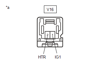
*a | Front view of wire harness connector (to Forward Recognition with Heater Hood Sub-assembly) |
(a) Measure the voltage according to the value(s) in the table below.
Standard Voltage:
|
Tester Connection | Condition |
Specified Condition |
|---|---|---|
|
V16-1 (IG1) - Body ground |
Ignition switch ON | 8 to 16 V |
|
Ignition switch off | Below 1.5 V |
| NG | | REPAIR OR REPLACE HARNESS OR CONNECTOR |
|
| 4. |
CHECK HARNESS AND CONNECTOR (FORWARD RECOGNITION WITH HEATER HOOD SUB-ASSEMBLY - FORWARD RECOGNITION CAMERA) |
(a) Disconnect the V6*1, V21*2 forward recognition camera connector.
- *1: Before Nov. 2021 Production
- *2: From Nov. 2021 Production
(b) Measure the resistance according to the value(s) in the table below.
Standard Resistance:
Before Nov. 2021 Production|
Tester Connection | Condition |
Specified Condition |
|---|---|---|
|
V16-2 (HTR) - V6-1 (HTR) |
Always | Below 1 Ω |
|
V16-2 (HTR) or V6-1 (HTR) - Body ground |
Always | 10 kΩ or higher |
|
Tester Connection | Condition |
Specified Condition |
|---|---|---|
|
V16-2 (HTR) - V21-1 (HTR) |
Always | Below 1 Ω |
|
V16-2 (HTR) or V21-1 (HTR) - Body ground |
Always | 10 kΩ or higher |
| OK | | REPLACE FORWARD RECOGNITION CAMERA |
| NG | | REPAIR OR REPLACE HARNESS OR CONNECTOR |
READ NEXT:
 Lost Communication with ECM/PCM "A" Missing Message (U010087,U012587,U012687,U012987,U014087)
DESCRIPTION When a malfunction is detected between various ECUs and sensors, these DTCs are stored.
DTC No. Detection Item
DTC Detection Condition Trouble Area
U010087 Lost Co
Internal Control Module Software Incompatibility Not Programmed (U030051,U030057)
DESCRIPTION The forward recognition camera receives vehicle information from the ECM via the CAN communication line.
When the forward recognition camera is unable to determine the vehicle informatio
Software Incompatibility with Body Control Module Not Programmed (U032251)
DESCRIPTION The forward recognition camera receives vehicle information from the main body ECU (multiplex network body ECU) via CAN communication.
DTC U032251 is stored when the forward recognition
SEE MORE:
Air Conditioning Panel
ComponentsCOMPONENTS ILLUSTRATION
*1 AIR CONDITIONING CONTROL ASSEMBLY
*2 NO. 1 METER HOOD CLUSTER
*3 NO. 2 INSTRUMENT PANEL GARNISH SUB-ASSEMBLY
*4 NO. 3 INSTRUMENT PANEL REGISTER ASSEMBLY RemovalREMOVAL PROCEDURE
1. REMOVE NO. 1 METER HOOD CLUSTER Click here
Components
COMPONENTS ILLUSTRATION
*A w/ Smart Key System
- -
*1 ECU INTEGRATION BOX RH
*2 LOWER INSTRUMENT PANEL SUB-ASSEMBLY
*3 CENTRAL GATEWAY ECU (NETWORK GATEWAY ECU)
- -
N*m (kgf*cm, ft.*lbf): Specified torque
- - ILLUSTRAT
