Toyota Camry (XV70): Roof Drip Side Finish Moulding
Components
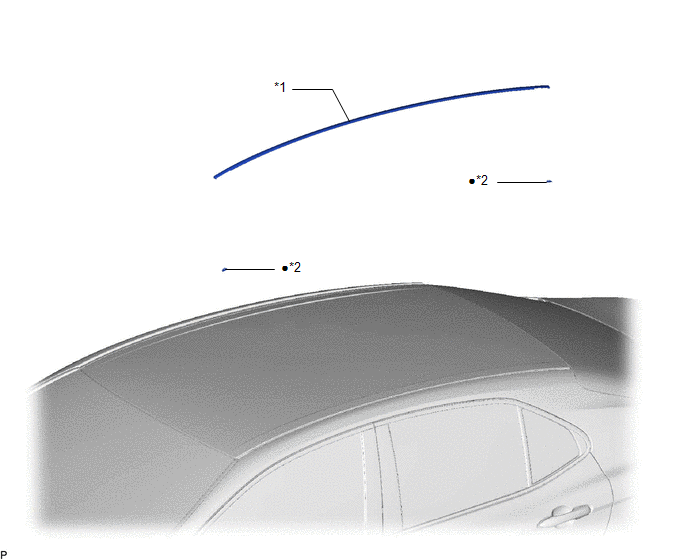
COMPONENTS
ILLUSTRATION
|
*1 | ROOF DRIP SIDE FINISH MOULDING |
*2 | ROOF DRIP SIDE FINISH MOULDING CLIP |
|
● | Non-reusable part |
- | - |
Removal
REMOVAL
CAUTION / NOTICE / HINT
HINT:
- Use the same procedure for the RH side and LH side.
- The following procedure is for the LH side.
PROCEDURE
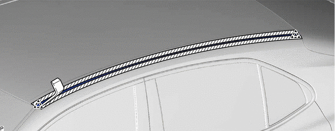
1. REMOVE ROOF DRIP SIDE FINISH MOULDING
(a) Apply protective tape around the roof drip side finish moulding as shown in the illustration.

.png) |
Protective Tape | - |
- |
(b) Using a moulding remover, disengage the 2 clips and remove the roof drip side finish moulding.
NOTICE:
- Do not remove the roof drip side finish moulding clips.
- If a roof drip side finish moulding clip is damaged or falls off, replace it with a new one.
Installation
INSTALLATION
CAUTION / NOTICE / HINT
HINT:
- Use the same procedure for the RH side and LH side.
- The following procedure is for the LH side.
PROCEDURE
1. INSTALL ROOF DRIP SIDE FINISH MOULDING CLIP
NOTICE:
When installing new roof drip side finish moulding clips, remove any double-sided tape remaining where the roof drip side finish moulding clips will be installed on the vehicle body and clean the vehicle body with a non-residue solvent.
| (a) Apply a 2 to 3 mm (0.0787 to 0.118 in.) bead of adhesive (3M DP-105 or equivalent) to each new roof drip side finish moulding clip. HINT: Adhesive strength (tensile strength): 13.7 MPa (140.0 kgf/cm2, 1987 psi) or more (when the temperature is 23 |
READ NEXT:
 Components
COMPONENTS ILLUSTRATION
*1 FRONT FENDER TO COWL SIDE SEAL
*2 NO. 1 WINDSHIELD OUTSIDE MOULDING CLIP
*3 NO. 3 WINDSHIELD OUTSIDE MOULDING CLIP
*4 WINDSHIELD
Removal
REMOVAL CAUTION / NOTICE / HINT
HINT:
Use the same procedure for the RH side and LH side.
The following procedure is for the LH side.
PROCEDURE 1. REMOVE FRONT FENDER TO COWL SIDE S
SEE MORE:
Problem Symptoms Table
PROBLEM SYMPTOMS TABLE
NOTICE:
Depending on the parts that are replaced during vehicle inspection or maintenance, performing initialization, registration or calibration may be needed. Refer to Precaution for Navigation System.
Click here
When replacing the radio and display receiver asse
System Description
SYSTEM DESCRIPTION GENERAL (a) The rear window defogger wire (back window glass) is attached to the inside of the rear window and defogs the window surface quickly when the rear window defogger switch is pressed. The indicator light on the switch illuminates while the system is operating. This syste
