Toyota Camry (XV70): Stereo Jack Adapter Assembly
Toyota Camry Repair Manual XV70 (2018-2024) / Audio, Visual, Telematics / Audio / Video / Stereo Jack Adapter Assembly
Components
COMPONENTS
ILLUSTRATION
|
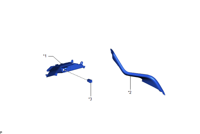
*1 | LOWER CENTER INSTRUMENT PANEL FINISH PANEL |
*2 | NO. 1 METER HOOD CLUSTER |
|
*3 | NO. 1 STEREO JACK ADAPTER ASSEMBLY |
- | - |
Removal
REMOVAL
PROCEDURE
1. REMOVE NO. 1 METER HOOD CLUSTER
Click here
.gif)
2. REMOVE LOWER CENTER INSTRUMENT PANEL FINISH PANEL
Click here
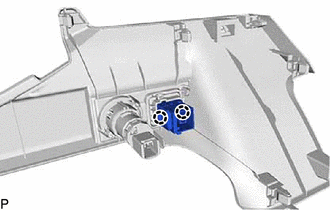
3. REMOVE NO. 1 STEREO JACK ADAPTER ASSEMBLY
| (a) Disengage the 2 claws and remove the No. 1 stereo jack adapter assembly. |
|
Installation
INSTALLATION
PROCEDURE
1. INSTALL NO. 1 STEREO JACK ADAPTER ASSEMBLY
(a) Engage the 2 claws to install the No. 1 stereo jack adapter assembly.
2. INSTALL LOWER CENTER INSTRUMENT PANEL FINISH PANEL
Click here
.gif)
3. INSTALL NO. 1 METER HOOD CLUSTER
Click here
READ NEXT:
 Back-up Battery
ComponentsCOMPONENTS ILLUSTRATION
*1 BACK-UP BATTERY
*2 TRANSCEIVER COVER RemovalREMOVAL CAUTION / NOTICE / HINT
The necessary procedures (adjustment, calibration, initializat
SEE MORE:
Main Microcomputer in Front Radar Sensor Calibration/Parameter Memory Failure (C1A8C46,C1A8D1C,C1A9000,C1A9100)
DESCRIPTION When an internal malfunction is detected in the millimeter wave radar sensor assembly, a DTC is stored.
DTC No. Detection Item
DTC Detection Condition Trouble Area
C1A8C46 Main Microcomputer in Front Radar Sensor Calibration/Parameter Memory Failure
When th
Parts Location
PARTS LOCATION ILLUSTRATION
*1 FRONT DOOR COURTESY LIGHT SWITCH ASSEMBLY (for LH)
*2 FRONT DOOR COURTESY LIGHT SWITCH ASSEMBLY (for RH)
*3 SLIDING ROOF SWITCH (ROOF CONSOLE BOX SUB-ASSEMBLY)
*4 SLIDING ROOF ECU (SLIDING ROOF DRIVE GEAR SUB-ASSEMBLY)
© 2023-2026 Copyright www.tocamry.com
