
Toyota Camry (XV70): System Diagram
Toyota Camry Repair Manual XV70 (2018-2024) / Vehicle Exterior / Window / Glass / Power Window Control System / System Diagram
SYSTEM DIAGRAM
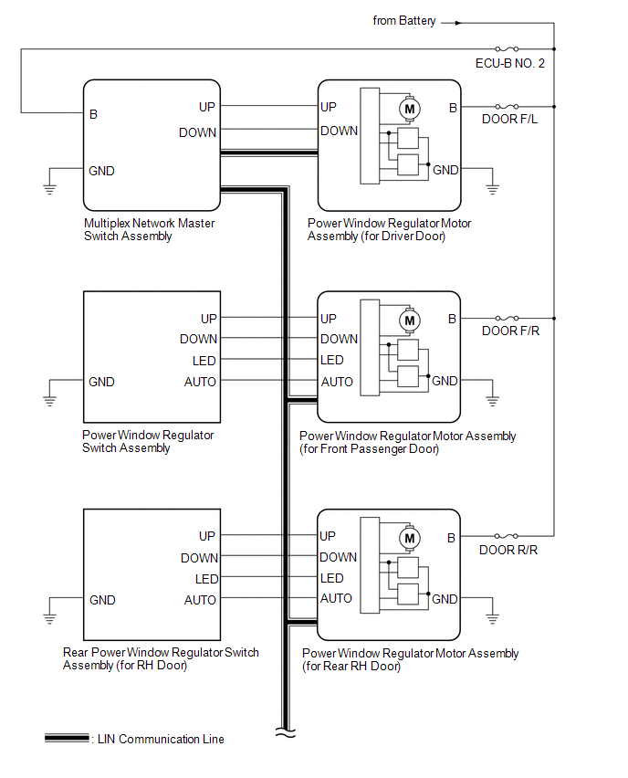
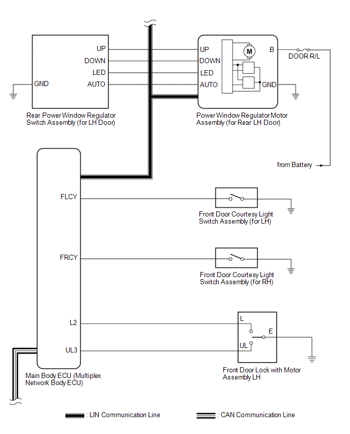
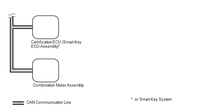 Communication Table
 |
Transmitting ECU | Receiving ECU |
Signal | Communication Method |
|---|---|---|---|
|
Multiplex Network Master Switch Assembly |
Power Window Regulator Motor Assembly (for Driver Door) |
Power window auto up and down signal |
LIN |
| Power window remote up and down signal |
LIN | |
| Main Body ECU (Multiplex Network Body ECU) |
| Power window operation permission signal |
LIN |
| Certification ECU (Smart Key ECU Assembly)* |
Main Body ECU (Multiplex Network Body ECU) | Wireless power window operation signal |
CAN |
| Main Body ECU (Multiplex Network Body ECU) |
Combination Meter Assembly | Window open warning request signal |
CAN |
- *: w/ Smart Key System
READ NEXT:
 System Description
SYSTEM DESCRIPTION POWER WINDOW CONTROL SYSTEM DESCRIPTION
(a) The power window control system controls the power window operation using the power window regulator motor assemblies. The main contro
How To Proceed With Troubleshooting
CAUTION / NOTICE / HINT
HINT:
Use the following procedure to troubleshoot the power window control system.
*: Use the Techstream.
PROCEDURE
1. VEHICLE BROUGHT TO WORKSHO
Operation Check
OPERATION CHECK CHECK WINDOW LOCK FUNCTION HINT:
Before performing the window lock switch operation check, make sure that the window lock switch is off (the switch is not pushed in).
(a) Turn t
SEE MORE:
Inspection
INSPECTION PROCEDURE 1. INSPECT OIL PUMP RELIEF VALVE
(a) Coat the oil pump relief valve with engine oil and check that it falls smoothly into the valve hole by its own weight.
HINT: If the oil pump relief valve does not fall smoothly, replace the timing chain cover assembly.
Components
COMPONENTS ILLUSTRATION
*1 AIR CLEANER CAP WITH AIR CLEANER HOSE
*2 THROTTLE BODY GASKET
*3 THROTTLE BODY WITH MOTOR ASSEMBLY
*4 VACUUM HOSE
*5 NO. 1 FUEL VAPOR FEED HOSE
*6 NO. 2 VENTILATION HOSE
*7 NO. 2 WATER BY-PASS HOSE
*8
© 2023-2026 Copyright www.tocamry.com
