Toyota Camry (XV70): Adjustment
ADJUSTMENT
CAUTION / NOTICE / HINT
The necessary procedures (adjustment, calibration, initialization, or registration) that must be performed after parts are removed and installed, or replaced during automatic transaxle fluid replacement are shown below.
Necessary Procedures After Parts Removed/Installed/Replaced|
Replaced Part or Performed Procedure |
Necessary Procedure | Effect/Inoperative Function when Necessary Procedure not Performed |
Link |
|---|---|---|---|
| Replacement of automatic transaxle fluid |
ATF thermal degradation estimate reset |
The value of the Data List item "ATF Thermal Degradation Estimate" is not estimated correctly. |
|
.gif)
PROCEDURE
1. PRECAUTIONS AND WORK DESCRIPTION
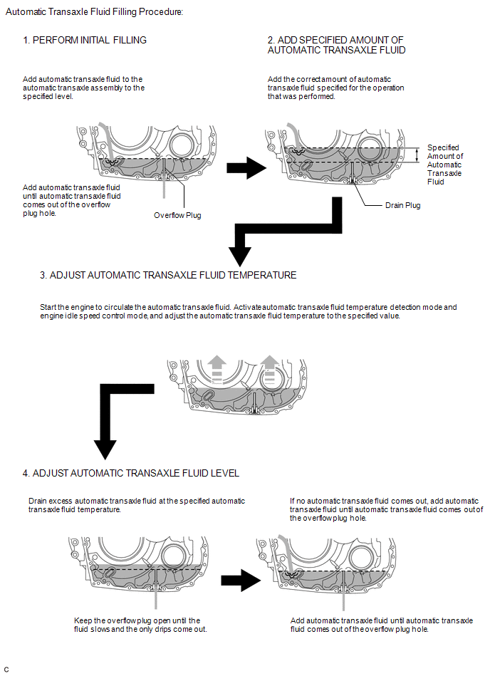
(a) The UA80E automatic transaxle assembly does not have an oil filler tube and oil level gauge. When adding automatic transaxle fluid, add automatic transaxle fluid through the refill hole on the automatic transaxle case sub-assembly. The automatic transaxle fluid level can be adjusted by draining excess automatic transaxle fluid (allowing excess automatic transaxle fluid to overflow) through the overflow plug of the transaxle housing.
HINT:
"Overflow" indicates the condition under which automatic transaxle fluid comes out of the overflow plug hole.
(b) Before adjusting the automatic transaxle fluid level, add the specified amount of automatic transaxle fluid when the engine is cold and warm up the engine to circulate the automatic transaxle fluid in the automatic transaxle assembly. Ensure that the automatic transaxle fluid temperature is as specified and the engine is idling.
(c) The UA80E automatic transaxle assembly requires Toyota Genuine ATF WS.
(d) The adjustment should be performed according to the procedures and notes.
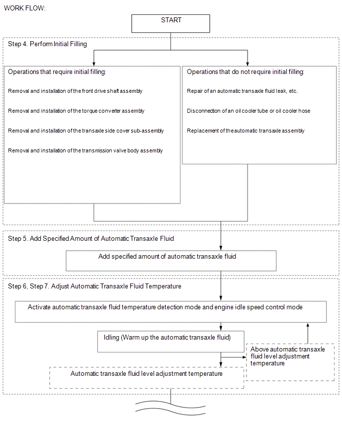
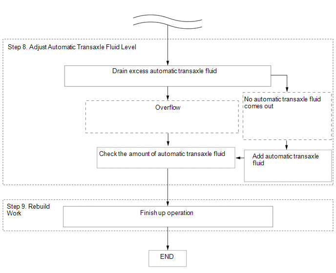
2. WORK FLOW
(a) The adjustment should be performed according to the procedure referenced in the work flow below.
3. PREPARATION WORK
(a) Lift the vehicle.
NOTICE:
Set the vehicle on a lift so that the vehicle is kept level when it is lifted up (make sure that the tilt angle from the front to rear and side to side of the vehicle is within +/- 1
READ NEXT:
 Precaution
PRECAUTION PRECAUTION FOR DISCONNECTING CABLE FROM NEGATIVE BATTERY TERMINAL
NOTICE: When disconnecting the cable from the negative (-) battery terminal, initialize the following system(s) after the
Definition Of Terms
DEFINITION OF TERMS
Term Definition
Monitor description Description of what the ECM monitors and how it detects malfunctions (monitoring purpose and details).
Related DTCs
SEE MORE:
Lost Communication with Blind Spot Monitor Slave Module (U0232)
DESCRIPTION This DTC is stored when the blind spot monitor sensor RH judges that there is a communication problem with the blind spot monitor sensor LH.
DTC No. Detection Item
DTC Detection Condition Trouble Area
U0232 Lost Communication with Blind Spot Monitor Slave Module
Inspection
INSPECTION PROCEDURE 1. INSPECT FUEL PUMP ASSEMBLY
(a) Measure the resistance according to the value(s) in the table below.
Standard Resistance:
Tester Connection Condition
Specified Condition
1 - 2 20°C (68°F)
0.45 to 0.55 Ω If the result is not
