Toyota Camry (XV70): IG Power Supply Voltage (C1551)
DESCRIPTION
When a problem occurs in the power source circuit, the fail-safe function works to stop the power assist.
|
DTC No. | Detection Item |
DTC Detection Condition |
Trouble Area | Warning Indicate |
Return-to-normal Condition |
Note |
|---|---|---|---|---|---|---|
| C1551 |
IG Power Supply Voltage |
When the PIG power supply voltage is normal, the IG power supply voltage is 18.5 V or higher |
| EPS warning light: Comes on |
The ECU judges the system has returned to normal |
- |
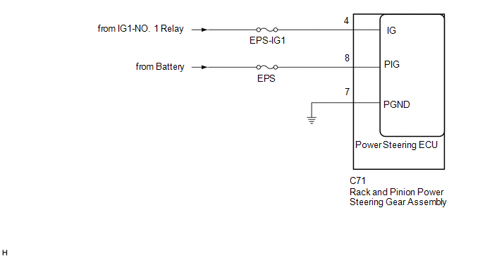
WIRING DIAGRAM
CAUTION / NOTICE / HINT
NOTICE:
- If the rack and pinion power steering gear assembly has been replaced, perform assist map writing and torque sensor zero point calibration.
Click here
.gif)
- Inspect the fuses for circuits related to this system before performing the following procedure.
PROCEDURE
|
1. | CHECK HARNESS AND CONNECTOR (BATTERY - RACK AND PINION POWER STEERING GEAR ASSEMBLY) |
(a) Disconnect the C71 rack and pinion power steering gear assembly connector.

|
*a | Front view of wire harness connector (to Rack and Pinion Power Steering Gear Assembly) |
- | - |
(b) Measure the voltage according to the value(s) in the table below.
Standard Voltage:
|
Tester Connection | Condition |
Specified Condition |
|---|---|---|
|
C71-4 (IG) - Body ground |
Ignition switch ON |
Below 18.5 V |
| NG | .gif) |
REPAIR OR REPLACE HARNESS OR CONNECTOR |
|
.gif)
|
2. | CHECK FOR DTC |
(a) Clear the DTCs.
Chassis > EMPS > Clear DTCs(b) Check for DTCs.
Chassis > EMPS > Trouble Codes|
Result | Proceed to |
|---|---|
|
DTC is output. | A |
|
DTC is not output. |
B |
| A | |
REPLACE RACK AND PINION POWER STEERING GEAR ASSEMBLY
|
| B | |
USE SIMULATION METHOD TO CHECK |
READ NEXT:
 PIG Power Supply Voltage (C1552,C1554)
DESCRIPTION When a problem occurs in the PIG power source and power supply relay system, the fail-safe function works to stop the power assist.
DTC No. Detection Item
DTC Detection Cond
Error in Matching of ECUs (C1567)
DESCRIPTION The power steering ECU (rack and pinion power steering gear assembly) determines whether an incompatible ECM, main body ECU (multiplex network body ECU) or skid control ECU (brake actuator
Assist Map Number Un-Writing (C1581)
DESCRIPTION This DTC will be stored if the power steering ECU (rack and pinion power steering gear assembly) determines that the assist map is not written in the ECU.
DTC No. Detection Item
SEE MORE:
Software Incompatibility with Body Control Module Not Programmed (U032251)
DESCRIPTION If the forward recognition camera cannot verify the vehicle information sent from the main body ECU (multiplex network body ECU), the forward recognition camera stores DTC U032251.
DTC No. Detection Item
DTC Detection Condition Trouble Area
DTC Output from
U03
Washer Fluid Level Warning Switch Circuit
DESCRIPTION When the washer fluid level is lower than a certain level, a warning message is displayed on the combination meter assembly. WIRING DIAGRAM
PROCEDURE
1.
READ VALUE USING TECHSTREAM (a) Connect the Techstream to the DLC3.
(b) Turn the ignition switch ON. (c) Turn the Te
