Toyota Camry (XV70): PIG Power Supply Voltage (C1552,C1554)
DESCRIPTION
When a problem occurs in the PIG power source and power supply relay system, the fail-safe function works to stop the power assist.
|
DTC No. | Detection Item |
DTC Detection Condition |
Trouble Area | Warning Indicate |
Return-to-normal Condition |
Note |
|---|---|---|---|---|---|---|
| C1552 |
PIG Power Supply Voltage |
PIG power source circuit malfunction |
| EPS warning light: Comes on |
Ignition switch is turned to ON again |
- |
| C1554 |
Power Supply Relay Failure |
Power source relay circuit malfunction |
| EPS warning light: Comes on |
Ignition switch is turned to ON again |
- |
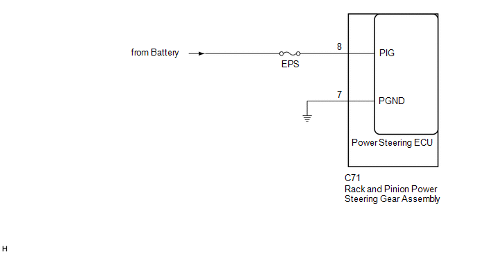
WIRING DIAGRAM
CAUTION / NOTICE / HINT
NOTICE:
- If the rack and pinion power steering gear assembly has been replaced, perform assist map writing and torque sensor zero point calibration.
Click here
.gif)
- Inspect the fuses for circuits related to this system before performing the following procedure.
PROCEDURE
|
1. | CHECK HARNESS AND CONNECTOR (RACK AND PINION POWER STEERING GEAR ASSEMBLY - BODY GROUND) |
(a) Disconnect the C71 rack and pinion power steering gear assembly connector.

|
*a | Front view of wire harness connector (to Rack and Pinion Power Steering Gear Assembly) |
- | - |
(b) Measure the voltage according to the value(s) in the table below.
Standard Voltage:
|
Tester Connection | Condition |
Specified Condition |
|---|---|---|
|
C71-8 (PIG) - Body ground |
Ignition switch ON |
9 to 16 V |
(c) Measure the resistance according to the value(s) in the table below.
Standard Resistance:
|
Tester Connection | Condition |
Specified Condition |
|---|---|---|
|
C71-7 (PGND) - Body ground |
Always | Below 1 Ω |
| OK | .gif) |
REPLACE RACK AND PINION POWER STEERING GEAR ASSEMBLY
|
| NG | |
REPAIR OR REPLACE HARNESS OR CONNECTOR |
READ NEXT:
 Error in Matching of ECUs (C1567)
DESCRIPTION The power steering ECU (rack and pinion power steering gear assembly) determines whether an incompatible ECM, main body ECU (multiplex network body ECU) or skid control ECU (brake actuator
Assist Map Number Un-Writing (C1581)
DESCRIPTION This DTC will be stored if the power steering ECU (rack and pinion power steering gear assembly) determines that the assist map is not written in the ECU.
DTC No. Detection Item
Assist Map Number Mismatch (C1582)
DESCRIPTION When an incorrect ECM, main body ECU (multiplex network body ECU) or skid control ECU (brake actuator assembly) is installed after the assist map has been written to the power steering ECU
SEE MORE:
SRS airbags
The SRS airbags inflate when the vehicle is subjected to certain
types of severe impacts that may cause significant injury to the
occupants. They work together with the seat belts to help reduce
the risk of death or serious injury.
SRS front airbags
SRS driver airbag/front passenger airbag
Engine Stalls
DESCRIPTION
Problem Symptom Suspected Area
Trouble Area
Engine speed fluctuation due to abnormal combustion
Idle speed too low or high
Strong engine vibration due to above symptoms
Ignition malfunction
Deviation in air fuel ratio (Excessive or i
