Toyota Camry (XV70): Adjustment
ADJUSTMENT
CAUTION / NOTICE / HINT
The necessary procedures (adjustment, calibration, initialization, or registration) that must be performed after completing the front wheel alignment procedure are shown below.
Necessary Procedures After Procedure Performed|
Replaced Part or Performed Procedure |
Necessary Procedure | Effect/Inoperative Function when Necessary Procedure not Performed |
Link |
|---|---|---|---|
| Front wheel alignment adjustment |
|
|
|
PROCEDURE
1. INSPECT TIRES
Click here 
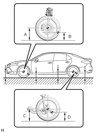
2. MEASURE VEHICLE HEIGHT
NOTICE:
- Before inspecting the wheel alignment, adjust the vehicle height to the specified value.
- Be sure to perform measurement on a level surface.
- If it is necessary to go under the vehicle for measurement, confirm that the parking brake is applied and the vehicle is secured with chocks.
- Inspect while the vehicle is unloaded.
- The standard value shown here is a value that is used for performing a wheel alignment and does not indicate the height of an actual vehicle.
(a) Bounce the vehicle up and down at the corners to stabilize the suspension.
| (b) Measure the vehicle height. Measurement Points:
Vehicle Height (Unloaded Vehicle):
|
| |||||||||||||||||||||||||
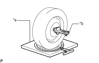
3. INSPECT CAMBER, CASTER AND STEERING AXIS INCLINATION
NOTICE:
Inspect while the vehicle is unloaded.
| (a) Install a camber-caster-kingpin gauge and place the front wheels on the center of a turning radius gauge. |
|
(b) Inspect the camber, caster and steering axis inclination.
Camber (Unloaded Vehicle):
|
Model | Camber Inclination |
Right-left Difference |
|---|---|---|
|
*1: for Mexico
*2: for TRD | ||
| AXVA70L-CEZNBA AXVA70L-CEZGBA | -0 | |
READ NEXT:
 Adjustment
ADJUSTMENT CAUTION / NOTICE / HINT
The necessary procedures (adjustment, calibration, initialization, or registration) that must be performed after completing the rear wheel alignment procedure are
SEE MORE:
Components
COMPONENTS ILLUSTRATION
*1 KNOCK CONTROL SENSOR (for Bank 1)
*2 KNOCK CONTROL SENSOR (for Bank 2)
N*m (kgf*cm, ft.*lbf): Specified torque
* For use with a union nut wrench
Parts Location
PARTS LOCATION ILLUSTRATION
*1 BRAKE ACTUATOR ASSEMBLY
- SKID CONTROL ECU *2
ECM *3
FRONT SPEED SENSOR LH
*4 FRONT SPEED SENSOR RH
*5 REAR SKID CONTROL SENSOR LH
*6 REAR SKID CONTROL SENSOR RH
*7 TRANSMISSION COUPLING ASSEMBLY
