
Toyota Camry (XV70): Air Conditioning Panel
Components
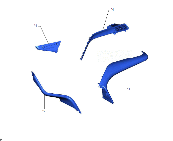
COMPONENTS
ILLUSTRATION
|
*1 | AIR CONDITIONING CONTROL ASSEMBLY |
*2 | NO. 1 METER HOOD CLUSTER |
|
*3 | NO. 2 INSTRUMENT PANEL GARNISH SUB-ASSEMBLY |
*4 | NO. 3 INSTRUMENT PANEL REGISTER ASSEMBLY |
Removal
REMOVAL
PROCEDURE
1. REMOVE NO. 1 METER HOOD CLUSTER
Click here
.gif)
2. REMOVE NO. 2 INSTRUMENT PANEL GARNISH SUB-ASSEMBLY
Click here
3. REMOVE NO. 3 INSTRUMENT PANEL REGISTER ASSEMBLY
Click here
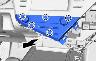
4. REMOVE AIR CONDITIONING CONTROL ASSEMBLY
(a) Disengage the 5 claws as shown in the illustration.
.png) |
Remove in this Direction |
(b) Disconnect the connector to remove the air conditioning control assembly.
Installation
INSTALLATION
PROCEDURE
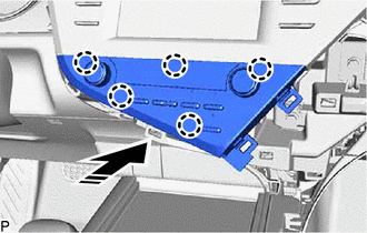
1. INSTALL AIR CONDITIONING CONTROL ASSEMBLY
(a) Connect the connector.
(b) Engage the 5 claws to install the air conditioning control assembly as shown in the illustration.
.png) |
Install in this Direction |
2. INSTALL NO. 3 INSTRUMENT PANEL REGISTER ASSEMBLY
Click here .gif)
3. INSTALL NO. 2 INSTRUMENT PANEL GARNISH SUB-ASSEMBLY
Click here
4. INSTALL NO. 1 METER HOOD CLUSTER
Click here
READ NEXT:
SEE MORE:
 Initialization
INITIALIZATION INITIALIZE POWER WINDOW CONTROL SYSTEM (ALL DOORS)
NOTICE:
When a door window regulator sub-assembly, power window regulator motor assembly, door glass or door glass run is reinstalled or replaced, the power window control system must be initialized. Functions such as the aut
Left Rear Wheel Speed Sensor Supply Voltage Circuit Short to Ground or Open (C14E614)
DESCRIPTION Refer to DTC C050C12 Click here
DTC No. Detection Item
DTC Detection Condition Trouble Area
C14E614 Left Rear Wheel Speed Sensor Supply Voltage Circuit Short to Ground or Open
An open or short in the speed sensor power supply circuit is detected for 0.1
