
Toyota Camry (XV70): On-vehicle Inspection
ON-VEHICLE INSPECTION
PROCEDURE
1. INSPECT AIR CONDITIONER PRESSURE SENSOR
(a) Check the wire harness.
(1) Disconnect the A18 air conditioner pressure sensor connector.
(2) Disconnect the K55 air conditioning amplifier assembly connector.
(3) Measure the resistance according to the value(s) in the table below.
Standard Resistance:
|
Tester Connection | Condition |
Specified Condition |
|---|---|---|
|
A18-1 (-) - K55-3 (SG-4) |
Always | Below 1 ? |
|
A18-2 (PR) - K55-24 (PRE) |
Always | Below 1 ? |
|
A18-3 (+) - K55-6 (S5-3) |
Always | Below 1 ? |
|
A18-1 (-) or K55-3 (SG-4) - Other terminals and body ground |
Always | 10 k? or higher |
|
A18-2 (PR) or K55-24 (PRE) - Other terminals and body ground |
Always | 10 k? or higher |
|
A18-3 (+) or K55-6 (S5-3) - Other terminals and body ground |
Always | 10 k? or higher |
If the resistance is not as specified, repair or replace the wire harness.
(4) Connect the K55 air conditioning amplifier assembly connector.
(5) Turn the ignition switch to ON.
(6) Measure the voltage according to the value(s) in the table below.
Standard Voltage:
|
Tester Connection | Condition |
Specified Condition |
|---|---|---|
|
A18-3 (+) - Body ground |
Ignition switch ON | 4.75 to 5.25 V |
If the voltage is not as specified, repair or replace the wire harness or replace air conditioning amplifier assembly.
(b) Check the air conditioner pressure sensor.
(1) Connect the A18 air conditioner pressure sensor connector.
(2) Install a manifold gauge set.
(3) Turn the A/C switch on.
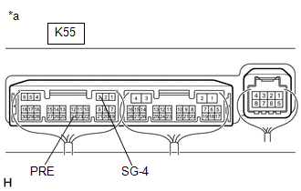
| (4) Measure the voltage according to the value(s) in the table below. HINT: Check from the rear of the connector while it is connected to the air conditioning amplifier assembly. Standard Voltage:
If the voltage is not as specified, replace the air conditioner pressure sensor. |
|
READ NEXT:
 Removal
REMOVAL PROCEDURE 1. RECOVER REFRIGERANT FROM REFRIGERATION SYSTEM
Click here 2. REMOVE AIR CONDITIONER PRESSURE SENSOR
(a) Disconnect the connector.
(b) Using a 27 mm deep
Installation
INSTALLATION PROCEDURE 1. INSTALL AIR CONDITIONER PRESSURE SENSOR
(a) Remove the vinyl tape from the air conditioner tube and accessory assembly.
(b) Sufficiently apply compressor oil to a new air c
SEE MORE:
Components
COMPONENTS ILLUSTRATION
*A for 7 Inch Display
*B for 9 Inch Display
*1 CENTER INSTRUMENT CLUSTER FINISH PANEL ASSEMBLY
*2 CENTER INSTRUMENT CLUSTER FINISH PANEL SUB-ASSEMBLY
*3 LOWER INSTRUMENT PANEL FINISH PANEL ASSEMBLY
*4 RADIO AND DISPLAY R
Manual Shifting Test
MANUAL SHIFTING TEST MANUAL SHIFTING TEST
HINT:
Using this test, it can be determined whether a problem is in an electrical circuit or if it is a mechanical problem in the transaxle.
If any abnormalities are found in the following test, the problem is in the transaxle itself.
(a) Dis
