
Toyota Camry (XV70): Installation
INSTALLATION
CAUTION / NOTICE / HINT
CAUTION:
The engine assembly with transaxle is very heavy. Be sure to follow the procedure described in the repair manual, or the engine lifter may suddenly drop or the engine assembly with transaxle may fall off the engine lifter.
PROCEDURE
1. INSTALL TORQUE CONVERTER ASSEMBLY
| (a) Set the key at the top of the front oil pump drive gear and put a matchmark on the transaxle housing. |
|
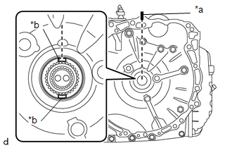
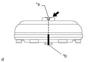
(b) Apply MP grease to place a matchmark on the torque converter assembly so that the position of its groove is clearly indicated.
|
*a | Groove |
|
*b | Matchmark |
 |
MP Grease |
| (c) Align the matchmark on the housing with the one on the torque converter assembly and engage the splines of the input shaft with the turbine runner splines. NOTICE:
|
|
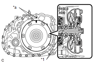
| (d) Rotate the torque converter assembly approximately 180 |
READ NEXT:
 Components
COMPONENTS ILLUSTRATION
*1 REAR ENGINE UNDER COVER LH
*2 FRONT FENDER APRON SEAL LH
*3 NO. 1 ENGINE UNDER COVER
*4 FRONT WHEEL OPENING EXTENSION PAD LH
*5
Replacement
REPLACEMENT CAUTION / NOTICE / HINT
The necessary procedures (adjustment, calibration, initialization, or registration) that must be performed after parts are removed and installed, or replaced duri
SEE MORE:
Throttle/Pedal Position Sensor/Switch "D" Circuit Short to Battery (P212012,P212014,P21201C,P21201F,P212099,P212512,P212514,P21251F,P21382B)
DESCRIPTION
HINT:
This Electronic Throttle Control System (ETCS) does not use a throttle cable.
These DTCs relate to the accelerator pedal position sensor.
The accelerator pedal position sensor is built into the accelerator pedal sensor assembly and has 2 sensor circuits: VPA (main) a
Installation
INSTALLATION PROCEDURE 1. INSTALL CLEARANCE WARNING ECU ASSEMBLY
(a) Engage the claw to install the clearance warning ECU assembly as shown in the illustration.
Install in this Direction 2. INSTALL ECU INTEGRATION BOX RH
Click here 3. INSTALL LOWER INSTRUMENT PANEL SUB-ASSE
