
Toyota Camry (XV70): Ambient Temperature Sensor Circuit (B1412)
DESCRIPTION
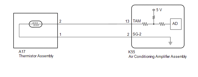
The thermistor assembly is installed in front of the cooler condenser assembly to detect the ambient temperature, which is used to control the air conditioning system. This sensor is connected to the air conditioning amplifier assembly and detects fluctuations in the ambient temperature. This data is used for controlling the cabin temperature. The sensor sends a signal to the air conditioning amplifier assembly. The resistance of the thermistor assembly changes in accordance with the ambient temperature. As the temperature decreases, the resistance increases. As the temperature increases, the resistance decreases.
The air conditioning amplifier assembly applies voltage (5 V) to the thermistor assembly and reads voltage changes due to changes in the resistance of the thermistor assembly.
|
DTC No. | Detection Item |
DTC Detection Condition | Trouble Area |
Memory |
|---|---|---|---|---|
| B1412 |
Ambient Temperature Sensor Circuit |
Open or short in ambient temperature sensor circuit |
| Memorized (4 sec. or more)* |
- *: The air conditioning amplifier assembly stores this DTC if the malfunction has occurred for the period of time indicated in the brackets.
HINT:
If the ambient temperature is approximately -52.9°C (-63.22°F) or lower, DTC B1412 may be stored even though the system is normal.
WIRING DIAGRAM
PROCEDURE
| 1. |
READ VALUE USING TECHSTREAM |
(a) Connect the Techstream to the DLC3.
(b) Turn the ignition switch to ON.
(c) Turn the Techstream on.
(d) Enter the following menus: Body Electrical / Air Conditioner / Data List.
(e) Read the Data List according to the display on the Techstream.
Body Electrical > Air Conditioner > Data List|
Tester Display | Measurement Item |
Range | Normal Condition |
Diagnostic Note |
|---|---|---|---|---|
|
Ambient Temp Sensor | Thermistor assembly |
Min.: -23.30°C (-9.94°F) Max.: 65.95°C (150.71°F) |
Actual ambient temperature displayed |
- |
|
Tester Display |
|---|
| Ambient Temp Sensor |
OK:
The display is as specified in the normal condition column.
| OK | .gif) | REPLACE AIR CONDITIONING AMPLIFIER ASSEMBLY
|
|
.gif)
| 2. |
INSPECT THERMISTOR ASSEMBLY |
(a) Remove the thermistor assembly.
Click here .gif)
(b) Inspect the thermistor assembly.
Click here
| NG | | REPLACE THERMISTOR ASSEMBLY
|
|
| 3. |
CHECK HARNESS AND CONNECTOR (THERMISTOR ASSEMBLY - AIR CONDITIONING AMPLIFIER ASSEMBLY) |
(a) Disconnect the K55 air conditioning amplifier assembly connector.
(b) Measure the resistance according to the value(s) in the table below.
Standard Resistance:
|
Tester Connection | Condition |
Specified Condition |
|---|---|---|
|
A17-2 (+) - K55-13 (TAM) |
Always | Below 1 ? |
|
A17-1 (-) - K55-2 (SG-2) |
Always | Below 1 ? |
|
A17-2 (+) or K55-13 (TAM) - Other terminals and body ground |
Always | 10 k? or higher |
|
A17-1 (-) or K55-2 (SG-2) - Other terminals and body ground |
Always | 10 k? or higher |
| OK | | REPLACE AIR CONDITIONING AMPLIFIER ASSEMBLY
|
| NG | | REPAIR OR REPLACE HARNESS OR CONNECTOR |
READ NEXT:
 Evaporator Temperature Circuit or Evaporator Fin Thermistor (B1413)
DESCRIPTION The No. 1 cooler thermistor is installed to the evaporator in the air conditioner unit to detect the temperature of the cooled air that has passed through the evaporator, which is used to
Compressor Lock (B1422)
DESCRIPTION The ECM sends the engine speed signal to the air conditioning amplifier assembly via CAN communication.
The air conditioning amplifier assembly reads the difference between compressor spe
Open in Pressure Sensor Circuit / Abnormal Refrigerant Pressure (B1423)
DESCRIPTION This DTC is stored if refrigerant pressure on the high pressure side is extremely low (196 kPaG (2.0 kgf/cm2, 28 psi) or less) or extremely high (2812 kPaG (28.7 kgf/cm2, 408 psi) or more)
SEE MORE:
Components
COMPONENTS ILLUSTRATION
*1 NO. 2 SLIDING ROOF SIDE GARNISH LH
*2 NO. 2 SLIDING ROOF SIDE GARNISH RH
*3 NO. 3 SLIDING ROOF SIDE GARNISH LH
*4 NO. 3 SLIDING ROOF SIDE GARNISH RH
*5 NO. 4 SLIDING ROOF SIDE GARNISH LH
*6 NO. 4 SLIDING ROOF
Disassembly
DISASSEMBLY PROCEDURE 1. REMOVE MAGNET STARTER SWITCH ASSEMBLY
(a) Remove the nut and disconnect the field coil lead wire from the magnet starter switch assembly.
(b) While holding the magnet starter switch assembly to the repair service starter kit, remove the 2 nuts.
