Toyota Camry (XV70): Automatic transmission
Shifting the shift lever
 Vehicles without a smart key
system:
While the engine switch is in the "ON" position and the brake
pedal depressed*, shift the shift lever while pushing the shift
release button on the shift knob.
Vehicles without a smart key
system:
While the engine switch is in the "ON" position and the brake
pedal depressed*, shift the shift lever while pushing the shift
release button on the shift knob.
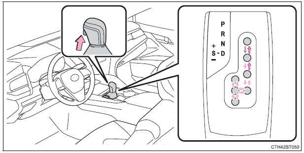
Vehicles with a smart key system: While the engine switch is in IGNITION ON mode and the brake pedal depressed*, shift the shift lever while pushing the shift release button on the shift knob.
 Shift the shift lever while
pushing the shift release button on
the shift knob.
Shift the shift lever while
pushing the shift release button on
the shift knob.
 Shift the shift lever normally.
When shifting the shift lever between P and D, make sure that the vehicle is completely stopped and the brake pedal is depressed.
*: For the vehicle be able to be shifted from P, the brake pedal must be depressed before the shift release button is pushed. If the shift release button is pushed first, the shift lock will not be released.
Shift position purpose
P - Parking the vehicle/starting the engine
R - Reversing
N - Neutral
D - Normal driving*1
S - S mode driving*2
*1: Shifting to the D position allows the system to select a gear suitable
for the
driving conditions. Setting the shift lever to the D position is recommended
for normal driving.
*2: Selecting shift ranges using S mode restricts the upper limit of the
possible
gear ranges, controls engine braking force, and prevents unnecessary
upshifting.
READ NEXT:
 Changing shift ranges in S mode
When the shift lever is in the S position, the shift lever or paddle shift
switches (if equipped) can be operated as follows:
Shift lever
Paddle shift switches (if
equipped)
Upshifting
D
Turn signal lever
Operating instructions
Right turn
Lane change to the right (move
the lever partway and release
it)
The right hand signals will flash 3
times.
Lane change to the left (move
the lever
Parking brake
Operating instructions
To set the parking brake, fully
depress the parking brake pedal
with your left foot while depressing
the brake pedal with your right
foot.
(Depressing the pedal again
r
SEE MORE:
System Description
SYSTEM DESCRIPTION LUGGAGE COMPARTMENT DOOR OPENER SYSTEM DESCRIPTION
(a) If the luggage compartment door opening switch assembly is pressed and the luggage compartment door is closed, a luggage compartment door lock assembly open operation signal is sent to the main body ECU (multiplex network b
Components
COMPONENTS ILLUSTRATION
*1 NO. 2 SLIDING ROOF SIDE GARNISH LH
*2 NO. 2 SLIDING ROOF SIDE GARNISH RH
*3 NO. 3 SLIDING ROOF SIDE GARNISH LH
*4 NO. 3 SLIDING ROOF SIDE GARNISH RH
*5 NO. 4 SLIDING ROOF SIDE GARNISH LH
*6 NO. 4 SLIDING ROOF
