Toyota Camry (XV70): Inspection
INSPECTION
PROCEDURE
1. INSPECT VACUUM SWITCHING VALVE (for Active Control Engine Mount System)
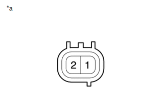
(a) Measure the resistance.
| (1) Measure the resistance according to the value(s) in the table below. Standard Resistance:
If the result is not as specified, replace the vacuum switching valve (for active control engine mount system). |
|
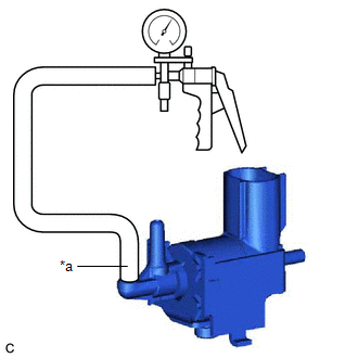
(b) Check the operation of the vacuum switching valve (for active control engine mount system).
| (1) Using a vacuum pump, apply a vacuum of 67 kPa (503 mmHg, 19.8 in. Hg) to port (F) and check that the vacuum is maintained. OK: Vacuum pressure holds. If the result is not as specified, replace the vacuum switching valve (for active control engine mount system). |
|
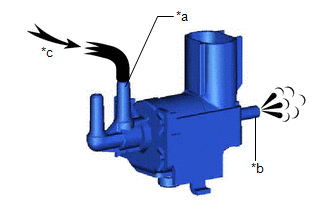
| (2) Check that air flows from port (E) to port (G). Standard: Air flows from port (E) to port (G). If the result is not as specified, replace the vacuum switching valve (for active control engine mount system). |
|
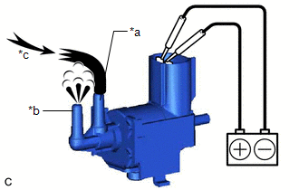
| (3) Apply battery voltage to the terminals and check that air flows from port (E) to port (F). Standard: Air flows from port (E) to port (F). If the result is not as specified, replace the vacuum switching valve (for active control engine mount system). |
|
READ NEXT:
 Installation
INSTALLATION PROCEDURE 1. INSTALL VACUUM SWITCHING VALVE (for Active Control Engine Mount System)
(a) Install the vacuum switching valve (for active control engine mount system) to the front engine
SEE MORE:
Data List / Active Test
DATA LIST / ACTIVE TEST ACTIVE TEST HINT:
Using the Techstream to perform Active Tests allows relays, VSVs, actuators and other items to be operated without removing any parts. This non-intrusive functional inspection can be very useful because intermittent operation may be discovered before part
Calibration
CALIBRATION DESCRIPTION (a) Refer to the table below and then perform the necessary operation according to the part to be replaced in order to perform calibration.
Parts to be Replaced / Operation
Necessary Operation
Skid control ECU (brake actuator assembly)
Perform acceler
