Toyota Camry (XV70): Check Bus 1 Line for Short to GND
DESCRIPTION
There may be a short circuit between one of the CAN bus lines and GND when there is no resistance between terminal 23 (CA1H) of the central gateway ECU (network gateway ECU) and terminal 4 (CG) of the DLC3, or terminal 8 (CA1L) of the central gateway ECU (network gateway ECU) and terminal 4 (CG) of the DLC3.
|
Symptom | Trouble Area |
|---|---|
|
There is no resistance between terminal 23 (CA1H) of the central gateway ECU (network gateway ECU) and terminal 4 (CG) of the DLC3, or terminal 8 (CA1L) of the central gateway ECU (network gateway ECU) and terminal 4 (CG) of the DLC3. |
|
WIRING DIAGRAM
w/ Parking Assist Monitor System or Panoramic View Monitor System.png) w/ Rear View Monitor System
w/ Rear View Monitor System
.png)
CAUTION / NOTICE / HINT
CAUTION:
When performing the confirmation driving pattern, obey all speed limits and traffic laws.
NOTICE:
- Because the order of diagnosis is important to allow correct diagnosis, make sure to begin troubleshooting using How to Proceed with Troubleshooting when CAN communication system related DTCs are output.
Click here
.gif)
- Before measuring the resistance of the CAN bus, turn the ignition switch off and leave the vehicle for 1 minute or more without operating the key or any switches, or opening or closing the doors. After that, disconnect the cable from the negative (-) battery terminal and leave the vehicle for 1 minute or more before measuring the resistance.
- After turning the ignition switch off, waiting time may be required before disconnecting the cable from the negative (-) battery terminal. Therefore, make sure to read the disconnecting the cable from the negative (-) battery terminal notices before proceeding with work.
Click here
- After performing repairs, perform the DTC check procedure and confirm that the DTCs are not output again.
DTC check procedure: Turn the ignition switch to ON and wait for 1 minute or more. Then operate the suspected malfunctioning system and drive the vehicle at 60 km/h (37 mph) or more for 5 minutes or more.
- After the repair, perform the CAN bus check and check that all the ECUs and sensors connected to the CAN communication system are displayed as normal.
Click here
HINT:
- Before disconnecting related connectors for inspection, push in on each connector body to check that the connector is not loose or disconnected.
- When a connector is disconnected, check that the terminals and connector body are not cracked, deformed or corroded.
PROCEDURE
|
1. | CHECK VEHICLE TYPE |
(a) Check vehicle type.
|
Result | Proceed to |
|---|---|
|
w/ Parking Assist Monitor System or Panoramic View Monitor System |
A |
| w/ Rear View Monitor System |
B |
| B |
.gif) | GO TO STEP 6 |
|
.gif)
| 2. |
CHECK FOR SHORT TO GND IN CAN BUS LINE (NO. 1 CAN JUNCTION CONNECTOR) |
(a) Disconnect the cable from the negative (-) battery terminal.
(b) Disconnect the A66 No. 1 CAN junction connector.
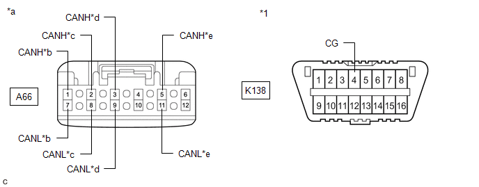
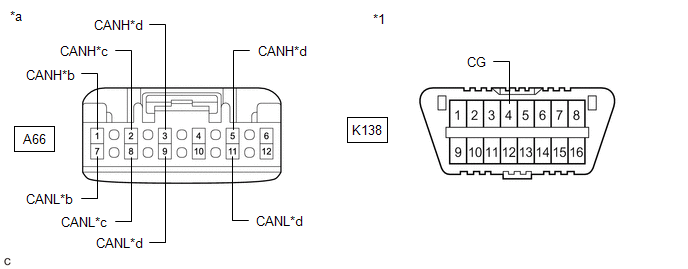
(c) Measure the resistance according to the value(s) in the table below.
|
*1 | DLC3 |
- | - |
|
*a | Front view of wire harness connector (to No. 1 CAN Junction Connector) |
*b | to Millimeter Wave Radar Sensor Assembly (w/ Front Camera System) |
|
*c | to Forward Recognition Camera (w/ Front Camera System) |
*d | to Central Gateway ECU (Network Gateway ECU) |
|
*e | to No. 5 CAN Junction Connector |
- | - |
Standard Resistance:
|
Tester Connection | Condition |
Specified Condition | Connected to |
|---|---|---|---|
|
A66-1 (CANH) - K138-4 (CG) |
Cable disconnected from negative (-) battery terminal |
200 Ω or higher |
Millimeter wave radar sensor assembly* |
|
A66-7 (CANL) - K138-4 (CG) | |||
|
A66-2 (CANH) - K138-4 (CG) |
Cable disconnected from negative (-) battery terminal |
200 Ω or higher |
Forward recognition camera* |
|
A66-8 (CANL) - K138-4 (CG) | |||
|
A66-3 (CANH) - K138-4 (CG) |
Cable disconnected from negative (-) battery terminal |
200 Ω or higher |
Central gateway ECU (network gateway ECU) |
|
A66-9 (CANL) - K138-4 (CG) | |||
|
A66-5 (CANH) - K138-4 (CG) |
Cable disconnected from negative (-) battery terminal |
200 Ω or higher |
No. 5 CAN junction connector |
|
A66-11 (CANL) - K138-4 (CG) |
- *: w/ Front Camera System
|
Result | Proceed to |
|---|---|
|
OK | A |
|
NG (Line to central gateway ECU (network gateway ECU)) |
B |
| NG (Line to No. 5 CAN junction connector) |
C |
| NG (Line to ECU or sensor) |
D |
| A |
| REPLACE NO. 1 CAN JUNCTION CONNECTOR |
| C |
| GO TO STEP 4 |
| D |
| GO TO STEP 8 |
|
| 3. |
CHECK FOR SHORT TO GND IN CAN BUS LINE (NO. 1 CAN JUNCTION CONNECTOR - CENTRAL GATEWAY ECU (NETWORK GATEWAY ECU)) |
(a) Disconnect the K76 central gateway ECU (network gateway ECU) connector.
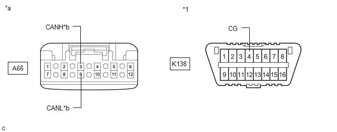
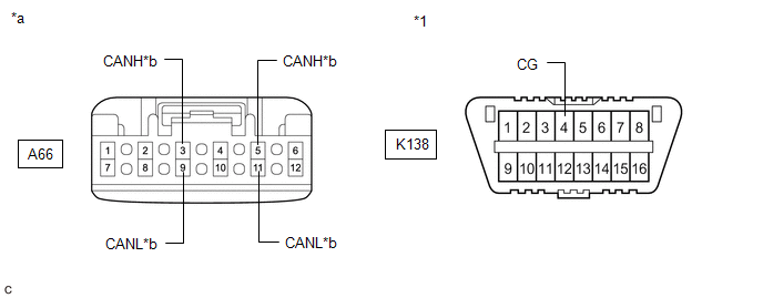
(b) Measure the resistance according to the value(s) in the table below.
|
*1 | DLC3 |
- | - |
|
*a | Front view of wire harness connector (to No. 1 CAN Junction Connector) |
*b | to Central Gateway ECU (Network Gateway ECU) |
Standard Resistance:
|
Tester Connection | Condition |
Specified Condition |
|---|---|---|
|
A66-3 (CANH) - K138-4 (CG) |
Cable disconnected from negative (-) battery terminal |
200 Ω or higher |
|
A66-9 (CANL) - K138-4 (CG) |
| OK | | REPLACE CENTRAL GATEWAY ECU (NETWORK GATEWAY ECU)
|
| NG | | REPAIR OR REPLACE CAN MAIN BUS LINE OR CONNECTOR (NO. 1 CAN JUNCTION CONNECTOR - CENTRAL GATEWAY ECU (NETWORK GATEWAY ECU)) |
| 4. |
CHECK FOR SHORT TO GND IN CAN BUS LINE (NO. 5 CAN JUNCTION CONNECTOR) |
(a) Disconnect the R98 No. 5 CAN junction connector.
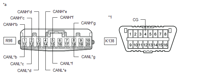
(b) Measure the resistance according to the value(s) in the table below.
|
*1 | DLC3 |
- | - |
|
*a | Front view of wire harness connector (to No. 5 CAN Junction Connector) |
*b | to Central Gateway ECU (Network Gateway ECU) |
|
*c | to Clearance Warning ECU Assembly (w/ Intuitive Parking Assist System) |
*d | to Blind Spot Monitor Sensor RH (w/ Blind Spot Monitor System) |
|
*e | to Rear Television Camera Assembly |
*f | to No. 1 CAN Junction Connector |
|
*g | to Television Camera Controller (w/ Panoramic View Monitor System) |
- | - |
Standard Resistance:
|
Tester Connection | Condition |
Specified Condition | Connected to |
|---|---|---|---|
|
R98-1 (CANH) - K138-4 (CG) |
Cable disconnected from negative (-) battery terminal |
200 Ω or higher |
Central gateway ECU (network gateway ECU) |
|
R98-11 (CANL) - K138-4 (CG) | |||
|
R98-2 (CANH) - K138-4 (CG) |
Cable disconnected from negative (-) battery terminal |
200 Ω or higher |
Clearance warning ECU assembly*1 |
|
R98-12 (CANL) - K138-4 (CG) | |||
|
R98-3 (CANH) - K138-4 (CG) |
Cable disconnected from negative (-) battery terminal |
200 Ω or higher |
Blind spot monitor sensor RH*2 |
|
R98-13 (CANL) - K138-4 (CG) | |||
|
R98-4 (CANH) - K138-4 (CG) |
Cable disconnected from negative (-) battery terminal |
200 Ω or higher |
Rear television camera assembly |
|
R98-14 (CANL) - K138-4 (CG) | |||
|
R98-5 (CANH) - K138-4 (CG) |
Cable disconnected from negative (-) battery terminal |
200 Ω or higher |
No. 1 CAN junction connector |
|
R98-15 (CANL) - K138-4 (CG) | |||
|
R98-8 (CANH) - K138-4 (CG) |
Cable disconnected from negative (-) battery terminal |
200 Ω or higher |
Television camera controller*3 |
|
R98-18 (CANL) - K138-4 (CG) |
- *1: w/ Intuitive Parking Assist System
- *2: w/ Blind Spot Monitor System
- *3: w/ Panoramic View Monitor System
|
Result | Proceed to |
|---|---|
|
OK | A |
|
NG (Line to central gateway ECU (network gateway ECU)) |
B |
| NG (Line to No. 1 CAN junction connector) |
C |
| NG (Line to ECU or sensor) |
D |
| A |
| REPLACE NO. 5 CAN JUNCTION CONNECTOR |
| C |
| REPAIR OR REPLACE CAN MAIN BUS LINE OR CONNECTOR (NO. 5 CAN JUNCTION CONNECTOR - NO. 1 CAN JUNCTION CONNECTOR) |
| D |
| GO TO STEP 8 |
|
| 5. |
CHECK FOR SHORT TO GND IN CAN BUS LINE (NO. 5 CAN JUNCTION CONNECTOR - CENTRAL GATEWAY ECU (NETWORK GATEWAY ECU)) |
(a) Disconnect the K76 central gateway ECU (network gateway ECU) connector.
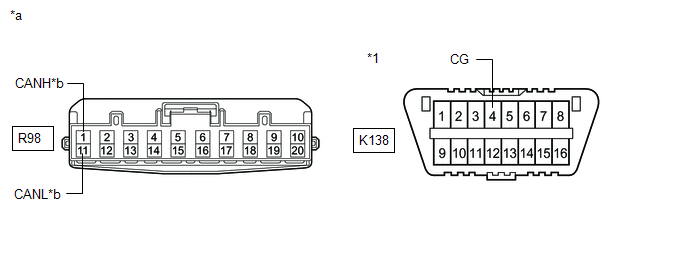
(b) Measure the resistance according to the value(s) in the table below.
|
*1 | DLC3 |
- | - |
|
*a | Front view of wire harness connector (to No. 5 CAN Junction Connector) |
*b | to Central Gateway ECU (Network Gateway ECU) |
Standard Resistance:
|
Tester Connection | Condition |
Specified Condition |
|---|---|---|
|
R98-1 (CANH) - K138-4 (CG) |
Cable disconnected from negative (-) battery terminal |
200 Ω or higher |
|
R98-11 (CANL) - K138-4 (CG) |
| OK | | REPLACE CENTRAL GATEWAY ECU (NETWORK GATEWAY ECU)
|
| NG | | REPAIR OR REPLACE CAN MAIN BUS LINE OR CONNECTOR (NO. 5 CAN JUNCTION CONNECTOR - CENTRAL GATEWAY ECU (NETWORK GATEWAY ECU)) |
| 6. |
CHECK FOR SHORT TO GND IN CAN BUS LINE (NO. 1 CAN JUNCTION CONNECTOR) |
(a) Disconnect the cable from the negative (-) battery terminal.
(b) Disconnect the A66 No. 1 CAN junction connector.
(c) Measure the resistance according to the value(s) in the table below.
|
*1 | DLC3 |
- | - |
|
*a | Front view of wire harness connector (to No. 1 CAN Junction Connector) |
*b | to Millimeter Wave Radar Sensor Assembly (w/ Front Camera System) |
|
*c | to Forward Recognition Camera (w/ Front Camera System) |
*d | to Central Gateway ECU (Network Gateway ECU) |
Standard Resistance:
|
Tester Connection | Condition |
Specified Condition | Connected to |
|---|---|---|---|
|
A66-1 (CANH) - K138-4 (CG) |
Cable disconnected from negative (-) battery terminal |
200 Ω or higher |
Millimeter wave radar sensor assembly* |
|
A66-7 (CANL) - K138-4 (CG) | |||
|
A66-2 (CANH) - K138-4 (CG) |
Cable disconnected from negative (-) battery terminal |
200 Ω or higher |
Forward recognition camera* |
|
A66-8 (CANL) - K138-4 (CG) | |||
|
A66-3 (CANH) - K138-4 (CG) |
Cable disconnected from negative (-) battery terminal |
200 Ω or higher |
Central gateway ECU (network gateway ECU) |
|
A66-9 (CANL) - K138-4 (CG) | |||
|
A66-5 (CANH) - K138-4 (CG) |
Cable disconnected from negative (-) battery terminal |
200 Ω or higher |
Central gateway ECU (network gateway ECU) |
|
A66-11 (CANL) - K138-4 (CG) |
- *: w/ Front Camera System
|
Result | Proceed to |
|---|---|
|
OK | A |
|
NG (Line to central gateway ECU (network gateway ECU)) |
B |
| NG (Line to ECU or sensor) |
C |
| A |
| REPLACE NO. 1 CAN JUNCTION CONNECTOR |
| C |
| GO TO STEP 8 |
|
| 7. |
CHECK FOR SHORT TO GND IN CAN BUS LINE (NO. 1 CAN JUNCTION CONNECTOR - CENTRAL GATEWAY ECU (NETWORK GATEWAY ECU)) |
(a) Disconnect the K76 central gateway ECU (network gateway ECU) connector.
(b) Measure the resistance according to the value(s) in the table below.
|
*1 | DLC3 |
- | - |
|
*a | Front view of wire harness connector (to No. 1 CAN Junction Connector) |
*b | to Central Gateway ECU (Network Gateway ECU) |
Standard Resistance:
|
Tester Connection | Condition |
Specified Condition |
|---|---|---|
|
A66-3 (CANH) - K138-4 (CG) |
Cable disconnected from negative (-) battery terminal |
200 Ω or higher |
|
A66-9 (CANL) - K138-4 (CG) | ||
|
A66-5 (CANH) - K138-4 (CG) |
Cable disconnected from negative (-) battery terminal |
200 Ω or higher |
|
A66-11 (CANL) - K138-4 (CG) |
| OK | | REPLACE CENTRAL GATEWAY ECU (NETWORK GATEWAY ECU)
|
| NG | | REPAIR OR REPLACE CAN MAIN BUS LINE OR CONNECTOR (NO. 1 CAN JUNCTION CONNECTOR - CENTRAL GATEWAY ECU (NETWORK GATEWAY ECU)) |
| 8. |
CHECK FOR SHORT TO GND IN CAN BUS LINE (ECU OR SENSOR) |
(a) Reconnect all wire harness connectors.
(b) Disconnect the connector that includes terminals CANH and CANL from the ECU or sensor to which the bus line shorted to GND is connected.
Click here
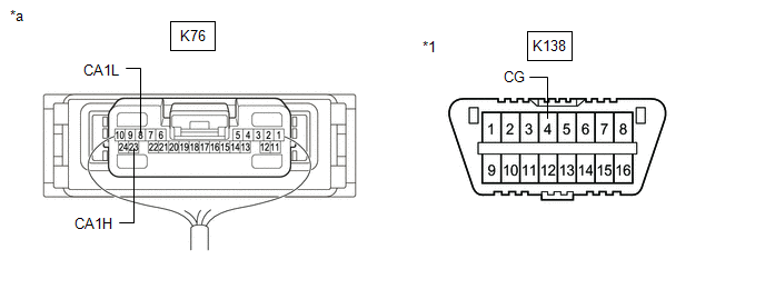
(c) Measure the resistance according to the value(s) in the table below.
|
*1 | DLC3 |
- | - |
|
*a | Component with harness connected (Central Gateway ECU (Network Gateway ECU)) |
- | - |
Standard Resistance:
|
Tester Connection | Condition |
Specified Condition |
|---|---|---|
|
K76-23 (CA1H) - K138-4 (CG) |
Cable disconnected from negative (-) battery terminal |
200 Ω or higher |
|
K76-8 (CA1L) - K138-4 (CG) |
HINT:
- If the resistance changes to 200 Ω or higher when the connector is disconnected from the ECU or sensor, there may be a short in the ECU or sensor.
- If the resistance does not become normal when the connector is disconnected from the ECU or sensor, check for a short to ground in the wire harness and repair or replace the wire harness or connector if necessary.
| OK | | REPLACE ECU OR SENSOR |
| NG | | REPAIR OR REPLACE HARNESS OR CONNECTOR |
READ NEXT:
 Open in One Side of Bus 1 Branch Line
DESCRIPTION When the CAN bus main lines are normal (no open, short to ground, short to +B or short between lines) and there is an ECU or sensor on the "Communication Bus Check" screen that is indicate
Open in Bus 2 Main Bus Line
DESCRIPTION There may be an open circuit in one of the CAN main bus lines when the resistance between terminals 18 (CA4H) and 17 (CA4L) of the central gateway ECU (network gateway ECU) is 70 Ω or
Check Bus 2 Lines for Short Circuit
DESCRIPTION There may be a short circuit between the CAN main bus lines and/or CAN branch lines when the resistance between terminals 18 (CA4H) and 17 (CA4L) of the central gateway ECU (network gatewa
SEE MORE:
Parts Location
PARTS LOCATION ILLUSTRATION
*A for 2WD
*B for AWD
*1 FRONT AXLE HUB SUB-ASSEMBLY RH
- FRONT SPEED SENSOR ROTOR RH
*2 FRONT SPEED SENSOR RH
*3 FRONT AXLE HUB SUB-ASSEMBLY LH
- FRONT SPEED SENSOR ROTOR LH
*4 FRONT SPEED SENSOR LH
AWD Warning does not Come ON
DESCRIPTION Refer to "4WD Warning Remains ON".
Click here WIRING DIAGRAM
Refer to "4WD Warning Remains ON". Click here
CAUTION / NOTICE / HINT
Refer to "4WD Warning Remains ON". Click here
PROCEDURE
1.
CHECK HARNESS AND CONNECTOR (a) Check that there is no looseness at
