Toyota Camry (XV70): Check Bus 2 Line for Short to +B
DESCRIPTION
There may be a short circuit between one of the CAN bus lines and +B when there is no resistance between terminal 18 (CA4H) of the central gateway ECU (network gateway ECU) and terminal 16 (BAT) of the DLC3, or terminal 17 (CA4L) of the central gateway ECU (network gateway ECU) and terminal 16 (BAT) of the DLC3.
|
Symptom | Trouble Area |
|---|---|
|
There is no resistance between terminal 18 (CA4H) of the central gateway ECU (network gateway ECU) and terminal 16 (BAT) of the DLC3, or terminal 17 (CA4L) of the central gateway ECU (network gateway ECU) and terminal 16 (BAT) of the DLC3. |
|
WIRING DIAGRAM
.png)
CAUTION / NOTICE / HINT
CAUTION:
When performing the confirmation driving pattern, obey all speed limits and traffic laws.
NOTICE:
- Because the order of diagnosis is important to allow correct diagnosis, make sure to begin troubleshooting using How to Proceed with Troubleshooting when CAN communication system related DTCs are output.
Click here
.gif)
- Before measuring the resistance of the CAN bus, turn the ignition switch off and leave the vehicle for 1 minute or more without operating the key or any switches, or opening or closing the doors. After that, disconnect the cable from the negative (-) battery terminal and leave the vehicle for 1 minute or more before measuring the resistance.
- After turning the ignition switch off, waiting time may be required before disconnecting the cable from the negative (-) battery terminal. Therefore, make sure to read the disconnecting the cable from the negative (-) battery terminal notices before proceeding with work.
Click here
- After performing repairs, perform the DTC check procedure and confirm that the DTCs are not output again.
DTC check procedure: Turn the ignition switch to ON and wait for 1 minute or more. Then operate the suspected malfunctioning system and drive the vehicle at 60 km/h (37 mph) or more for 5 minutes or more.
- After the repair, perform the CAN bus check and check that all the ECUs and sensors connected to the CAN communication system are displayed as normal.
Click here
HINT:
- Before disconnecting related connectors for inspection, push in on each connector body to check that the connector is not loose or disconnected.
- When a connector is disconnected, check that the terminals and connector body are not cracked, deformed or corroded.
PROCEDURE
|
1. | CHECK FOR SHORT TO +B IN CAN BUS LINE (NO. 2 CAN JUNCTION CONNECTOR) |
(a) Disconnect the cable from the negative (-) battery terminal.
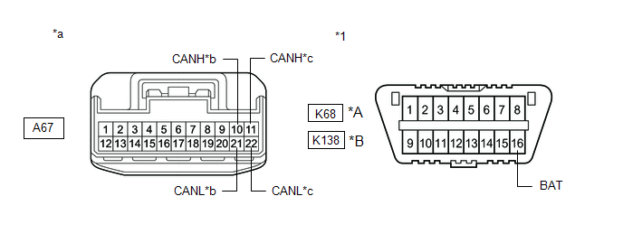
(b) Disconnect the A67 No. 2 CAN junction connector.
(c) Measure the resistance according to the value(s) in the table below.
|
*A | Before Jul. 2018 Production |
*B | From Jul. 2018 Production |
|
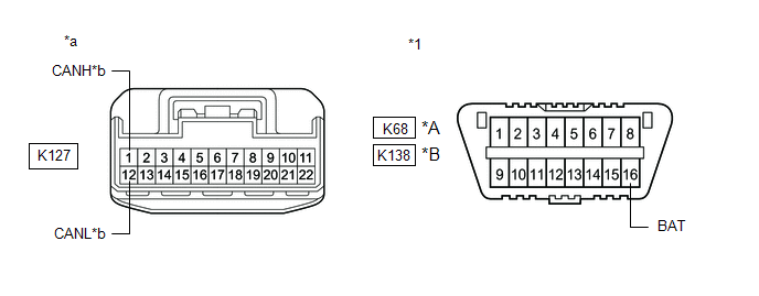
*1 | DLC3 |
- | - |
|
*a | Front view of wire harness connector (to No. 2 CAN Junction Connector) |
*b | to No. 4 CAN Junction Connector |
|
*c | to ECM |
- | - |
Standard Resistance:
Before Jul. 2018 Production:|
Tester Connection | Condition |
Specified Condition | Connected to |
|---|---|---|---|
|
A67-10 (CANH) - K68-16 (BAT) |
Cable disconnected from negative (-) battery terminal |
6 kΩ or higher |
No. 4 CAN junction connector |
|
A67-21 (CANL) - K68-16 (BAT) | |||
|
A67-11 (CANH) - K68-16 (BAT) |
Cable disconnected from negative (-) battery terminal |
6 kΩ or higher |
ECM |
| A67-22 (CANL) - K68-16 (BAT) |
|
Tester Connection | Condition |
Specified Condition | Connected to |
|---|---|---|---|
|
A67-10 (CANH) - K138-16 (BAT) |
Cable disconnected from negative (-) battery terminal |
6 kΩ or higher |
No. 4 CAN junction connector |
|
A67-21 (CANL) - K138-16 (BAT) | |||
|
A67-11 (CANH) - K138-16 (BAT) |
Cable disconnected from negative (-) battery terminal |
6 kΩ or higher |
ECM |
| A67-22 (CANL) - K138-16 (BAT) |
|
Result | Proceed to |
|---|---|
|
OK | A |
|
NG (Line to ECM) | B |
|
NG (Line to No. 4 CAN junction connector) |
C |
| A |
.gif) | REPLACE NO. 2 CAN JUNCTION CONNECTOR |
| C |
| GO TO STEP 3 |
|
.gif)
| 2. |
CHECK FOR SHORT TO +B IN CAN BUS LINE (NO. 2 CAN JUNCTION CONNECTOR - ECM) |
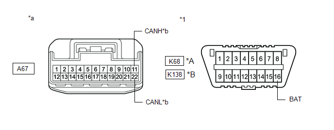
(a) Disconnect the A21 or A24 ECM connector.
(b) Measure the resistance according to the value(s) in the table below.
|
*A | Before Jul. 2018 Production |
*B | From Jul. 2018 Production |
|
*1 | DLC3 |
- | - |
|
*a | Front view of wire harness connector (to No. 2 CAN Junction Connector) |
*b | to ECM |
Standard Resistance:
Before Jul. 2018 Production:|
Tester Connection | Condition |
Specified Condition |
|---|---|---|
|
A67-11 (CANH) - K68-16 (BAT) |
Cable disconnected from negative (-) battery terminal |
6 kΩ or higher |
|
A67-22 (CANL) - K68-16 (BAT) |
|
Tester Connection | Condition |
Specified Condition |
|---|---|---|
|
A67-11 (CANH) - K138-16 (BAT) |
Cable disconnected from negative (-) battery terminal |
6 kΩ or higher |
|
A67-22 (CANL) - K138-16 (BAT) |
|
Result | Proceed to |
|---|---|
|
OK (for A25A-FKS) | A |
|
OK (for 2GR-FKS) | B |
|
NG | C |
| A |
| REPLACE ECM
|
| B |
| REPLACE ECM
|
| C |
| REPAIR OR REPLACE CAN MAIN BUS LINE OR CONNECTOR (NO. 2 CAN JUNCTION CONNECTOR - ECM) |
| 3. |
CHECK FOR SHORT TO +B IN CAN BUS LINE (NO. 4 CAN JUNCTION CONNECTOR - NO. 2 CAN JUNCTION CONNECTOR) |
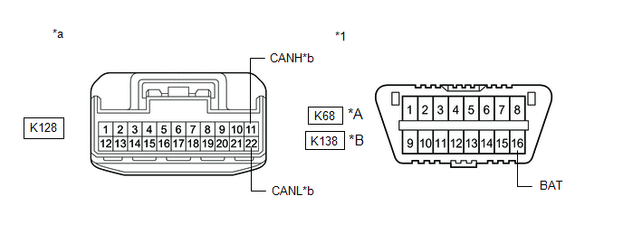
(a) Disconnect the K128 No. 4 CAN junction connector.
(b) Measure the resistance according to the value(s) in the table below.
|
*A | Before Jul. 2018 Production |
*B | From Jul. 2018 Production |
|
*1 | DLC3 |
- | - |
|
*a | Front view of wire harness connector (to No. 4 CAN Junction Connector) |
*b | to No. 2 CAN Junction Connector |
Standard Resistance:
Before Jul. 2018 Production:|
Tester Connection | Condition |
Specified Condition | Connected to |
|---|---|---|---|
|
K128-11 (CANH) - K68-16 (BAT) |
Cable disconnected from negative (-) battery terminal |
6 kΩ or higher |
No. 2 CAN junction connector |
|
K128-22 (CANL) - K68-16 (BAT) |
|
Tester Connection | Condition |
Specified Condition | Connected to |
|---|---|---|---|
|
K128-11 (CANH) - K138-16 (BAT) |
Cable disconnected from negative (-) battery terminal |
6 kΩ or higher |
No. 2 CAN junction connector |
|
K128-22 (CANL) - K138-16 (BAT) |
| NG | | REPAIR OR REPLACE CAN MAIN BUS LINE OR CONNECTOR (NO. 4 CAN JUNCTION CONNECTOR - NO. 2 CAN JUNCTION CONNECTOR) |
|
| 4. |
CHECK FOR SHORT TO +B IN CAN BUS LINE (NO. 4 CAN JUNCTION CONNECTOR) |
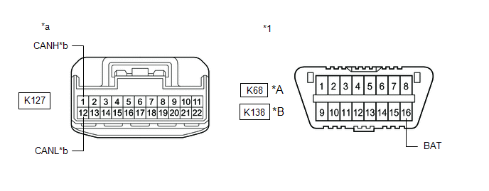
(a) Disconnect the K127 No. 4 CAN junction connector.
(b) Measure the resistance according to the value(s) in the table below.
|
*A | Before Jul. 2018 Production |
*B | From Jul. 2018 Production |
|
*1 | DLC3 |
- | - |
|
*a | Front view of wire harness connector (to No. 4 CAN Junction Connector) |
*b | to Central Gateway ECU (Network Gateway ECU) |
Standard Resistance:
Before Jul. 2018 Production:|
Tester Connection | Condition |
Specified Condition | Connected to |
|---|---|---|---|
|
K127-1 (CANH) - K68-16 (BAT) |
Cable disconnected from negative (-) battery terminal |
6 kΩ or higher |
Central gateway ECU (network gateway ECU) |
|
K127-12 (CANL) - K68-16 (BAT) |
|
Tester Connection | Condition |
Specified Condition | Connected to |
|---|---|---|---|
|
K127-1 (CANH) - K138-16 (BAT) |
Cable disconnected from negative (-) battery terminal |
6 kΩ or higher |
Central gateway ECU (network gateway ECU) |
|
K127-12 (CANL) - K138-16 (BAT) |
| OK | | REPLACE NO. 4 CAN JUNCTION CONNECTOR |
|
| 5. |
CHECK FOR SHORT TO +B IN CAN BUS LINE (NO. 4 CAN JUNCTION CONNECTOR - CENTRAL GATEWAY ECU (NETWORK GATEWAY ECU)) |
(a) Disconnect the K76 central gateway ECU (network gateway ECU) connector.
(b) Measure the resistance according to the value(s) in the table below.
|
*A | Before Jul. 2018 Production |
*B | From Jul. 2018 Production |
|
*1 | DLC3 |
- | - |
|
*a | Front view of wire harness connector (to No. 4 CAN Junction Connector) |
*b | to Central Gateway ECU (Network Gateway ECU) |
Standard Resistance:
Before Jul. 2018 Production:|
Tester Connection | Condition |
Specified Condition |
|---|---|---|
|
K127-1 (CANH) - K68-16 (BAT) |
Cable disconnected from negative (-) battery terminal |
6 kΩ or higher |
|
K127-12 (CANL) - K68-16 (BAT) |
|
Tester Connection | Condition |
Specified Condition |
|---|---|---|
|
K127-1 (CANH) - K138-16 (BAT) |
Cable disconnected from negative (-) battery terminal |
6 kΩ or higher |
|
K127-12 (CANL) - K138-16 (BAT) |
| OK | | REPLACE CENTRAL GATEWAY ECU (NETWORK GATEWAY ECU)
|
| NG | | REPAIR OR REPLACE CAN MAIN BUS LINE OR CONNECTOR (NO. 4 CAN JUNCTION CONNECTOR - CENTRAL GATEWAY ECU (NETWORK GATEWAY ECU)) |
READ NEXT:
 Check Bus 2 Line for Short to GND
DESCRIPTION There may be a short circuit between one of the CAN bus lines and GND when there is no resistance between terminal 18 (CA4H) of the central gateway ECU (network gateway ECU) and terminal 4
Open in Bus 3 Main Bus Line
DESCRIPTION There may be an open circuit in one of the CAN main bus lines when the resistance between terminals 6 (CA3H) and 21 (CA3L) of the central gateway ECU (network gateway ECU) is 70 Ω or
Check Bus 3 Lines for Short Circuit
DESCRIPTION There may be a short circuit between the CAN main bus lines and/or CAN branch lines when the resistance between terminals 6 (CA3H) and 21 (CA3L) of the central gateway ECU (network gateway
SEE MORE:
Parts Location
PARTS LOCATION ILLUSTRATION
*1 FORWARD RECOGNITION CAMERA
*2 FORWARD RECOGNITION WITH HEATER HOOD SUB-ASSEMBLY
*3 SKID CONTROL ECU (BRAKE ACTUATOR ASSEMBLY)
*4 ECM ILLUSTRATION
*1 STEERING SENSOR
*2 MAIN BODY ECU (MULTIPLEX NETWORK BODY EC
Emergency flashers
The emergency flashers are used to warn other drivers when the
vehicle has to be stopped on the road due to a breakdown, etc.
Press the switch.
All the turn signal lights will flash.
To turn them off, press the switch
once again.
■Emergency flashers
If the emergency flashers are us
