Toyota Camry (XV70): Check Bus 3 Lines for Short Circuit
DESCRIPTION
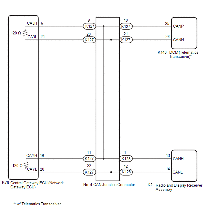
There may be a short circuit between the CAN main bus lines and/or CAN branch lines when the resistance between terminals 6 (CA3H) and 21 (CA3L) of the central gateway ECU (network gateway ECU) is below 54 Ω.
|
Symptom | Trouble Area |
|---|---|
|
Resistance between terminals 6 (CA3H) and 21 (CA3L) of the central gateway ECU (network gateway ECU) is below 54 Ω. |
|
WIRING DIAGRAM
CAUTION / NOTICE / HINT
CAUTION:
When performing the confirmation driving pattern, obey all speed limits and traffic laws.
NOTICE:
- Because the order of diagnosis is important to allow correct diagnosis, make sure to begin troubleshooting using How to Proceed with Troubleshooting when CAN communication system related DTCs are output.
Click here
.gif)
- Before measuring the resistance of the CAN bus, turn the ignition switch off and leave the vehicle for 1 minute or more without operating the key or any switches, or opening or closing the doors. After that, disconnect the cable from the negative (-) battery terminal and leave the vehicle for 1 minute or more before measuring the resistance.
- After turning the ignition switch off, waiting time may be required before disconnecting the cable from the negative (-) battery terminal. Therefore, make sure to read the disconnecting the cable from the negative (-) battery terminal notices before proceeding with work.
Click here
- After performing repairs, perform the DTC check procedure and confirm that the DTCs are not output again.
DTC check procedure: Turn the ignition switch to ON and wait for 1 minute or more. Then operate the suspected malfunctioning system and drive the vehicle at 60 km/h (37 mph) or more for 5 minutes or more.
- After the repair, perform the CAN bus check and check that all the ECUs and sensors connected to the CAN communication system are displayed as normal.
Click here
- Before replacing the DCM (telematics transceiver), refer to Registration.
- w/ Smart Key System
Click here
- w/o Smart Key System
Click here
- w/ Smart Key System
HINT:
- Before disconnecting related connectors for inspection, push in on each connector body to check that the connector is not loose or disconnected.
- When a connector is disconnected, check that the terminals and connector body are not cracked, deformed or corroded.
PROCEDURE
|
1. | CHECK FOR SHORT IN CAN BUS LINES (NO. 4 CAN JUNCTION CONNECTOR) |
(a) Disconnect the cable from the negative (-) battery terminal.
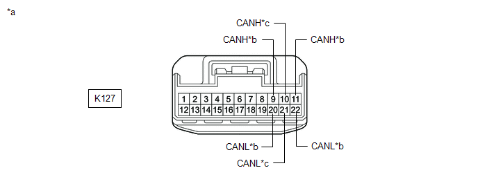
(b) Disconnect the K127 No. 4 CAN junction connector.
(c) Measure the resistance according to the value(s) in the table below.
|
*a | Front view of wire harness connector (to No. 4 CAN Junction Connector) |
*b | to Central Gateway ECU (Network Gateway ECU) |
|
*c | to DCM (Telematics Transceiver) (w/ Telematics Transceiver) |
- | - |
Standard Resistance:
|
Tester Connection | Condition |
Specified Condition | Connected to |
|---|---|---|---|
|
K127-9 (CANH) - K127-20 (CANL) |
Cable disconnected from negative (-) battery terminal |
108 to 132 Ω | Central gateway ECU (network gateway ECU) |
|
K127-10 (CANH) - K127-21 (CANL) |
Cable disconnected from negative (-) battery terminal |
200 Ω or higher | DCM (telematics transceiver)* |
|
K127-11 (CANH) - K127-22 (CANL) |
Cable disconnected from negative (-) battery terminal |
108 to 132 Ω | Central gateway ECU (network gateway ECU) |
- *: w/ Telematics Transceiver
|
Result | Proceed to |
|---|---|
|
OK | A |
|
NG (Line to central gateway ECU (network gateway ECU)) |
B |
| NG (Line to ECU or sensor) |
C |
| B |
.gif) | GO TO STEP 3 |
| C |
| GO TO STEP 4 |
|
.gif)
| 2. |
CHECK FOR SHORT IN CAN BUS LINES (NO. 4 CAN JUNCTION CONNECTOR) |
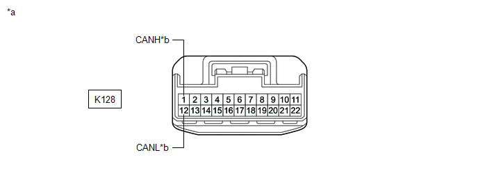
(a) Disconnect the K128 No. 4 CAN junction connector.
(b) Measure the resistance according to the value(s) in the table below.
|
*a | Front view of wire harness connector (to No. 4 CAN Junction Connector) |
*b | to Radio and Display Receiver Assembly |
Standard Resistance:
|
Tester Connection | Condition |
Specified Condition | Connected to |
|---|---|---|---|
|
K128-1 (CANH) - K128-12 (CANL) |
Cable disconnected from negative (-) battery terminal |
200 Ω or higher | Radio and display receiver assembly |
| OK | | REPLACE NO. 4 CAN JUNCTION CONNECTOR |
| NG | | GO TO STEP 4 |
| 3. |
CHECK FOR SHORT IN CAN BUS LINES (NO. 4 CAN JUNCTION CONNECTOR - CENTRAL GATEWAY ECU (NETWORK GATEWAY ECU)) |
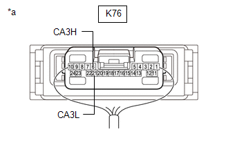
(a) Disconnect the K76 central gateway ECU (network gateway ECU) connector.
(b) Measure the resistance according to the value(s) in the table below.
.png)
|
*a | Front view of wire harness connector (to No. 4 CAN Junction Connector) |
*b | to Central Gateway ECU (Network Gateway ECU) |
Standard Resistance:
|
Tester Connection | Condition |
Specified Condition |
|---|---|---|
|
K127-9 (CANH) - K127-20 (CANL) |
Cable disconnected from negative (-) battery terminal |
1 MΩ or higher |
|
K127-11 (CANH) - K127-22 (CANL) |
Cable disconnected from negative (-) battery terminal |
1 MΩ or higher |
| OK | | REPLACE CENTRAL GATEWAY ECU (NETWORK GATEWAY ECU)
|
| NG | | REPAIR OR REPLACE CAN MAIN BUS LINES OR CONNECTOR (NO. 4 CAN JUNCTION CONNECTOR - CENTRAL GATEWAY ECU (NETWORK GATEWAY ECU)) |
| 4. |
CHECK FOR SHORT IN CAN BUS LINES (ECU OR SENSOR) |
(a) Reconnect all wire harness connectors.
(b) Disconnect the connector that includes terminals CANH and CANL from the ECU or sensor to which the short circuited branch line is connected.
Click here
| (c) Measure the resistance according to the value(s) in the table below. Standard Resistance:
HINT:
|
|
| OK | | REPLACE ECU OR SENSOR |
| NG | | REPAIR OR REPLACE HARNESS OR CONNECTOR |
READ NEXT:
 Check Bus 3 Line for Short to +B
DESCRIPTION There may be a short circuit between one of the CAN bus lines and +B when there is no resistance between terminal 6 (CA3H) of the central gateway ECU (network gateway ECU) and terminal 16
Check Bus 3 Line for Short to GND
DESCRIPTION There may be a short circuit between one of the CAN bus lines and GND when there is no resistance between terminal 6 (CA3H) of the central gateway ECU (network gateway ECU) and terminal 4
Open in One Side of Bus 3 Branch Line
DESCRIPTION When the CAN bus main lines are normal (no open, short to ground, short to +B or short between lines) and there is an ECU or sensor on the "Communication Bus Check" screen that is indicate
SEE MORE:
Open in Outer Mirror Indicator(Slave) (C1AB5)
DESCRIPTION This DTC is stored when the blind spot monitor sensor LH detects an open in the outer rear view mirror indicator LH.
DTC No. Detection Item
DTC Detection Condition Trouble Area
C1AB5 Open in Outer Mirror Indicator(Slave) Both of the following conditions are met
Components
COMPONENTS ILLUSTRATION
*1 FUEL DELIVERY PIPE RH
*2 FUEL DELIVERY PIPE WITH SENSOR ASSEMBLY LH
*3 FUEL INJECTOR ASSEMBLY
*4 FUEL INJECTOR SEAL
*5 NO. 2 FUEL PIPE SUB-ASSEMBLY
*6 WIRE HARNESS CLAMP BRACKET
*7 NO. 3 FUEL INJECTOR BACK-U
