
Toyota Camry (XV70): Communication Malfunction (Bus Ic) (B1497)
DESCRIPTION
The air conditioning harness assembly connects the air conditioning amplifier assembly and the servo motors. The air conditioning amplifier assembly supplies power and sends operation instructions to each servo motor through the air conditioning harness assembly. Each servo motor sends damper position information to the air conditioning amplifier assembly.
|
DTC No. | Detection Item |
DTC Detection Condition | Trouble Area |
Memory |
|---|---|---|---|---|
| B1497 |
Communication Malfunction (Bus Ic) |
Error or open in communication line |
| Memorized (10 sec. or more)* |
- *: The air conditioning amplifier assembly stores this DTC if the malfunction has occurred for the period of time indicated in the brackets.
WIRING DIAGRAM
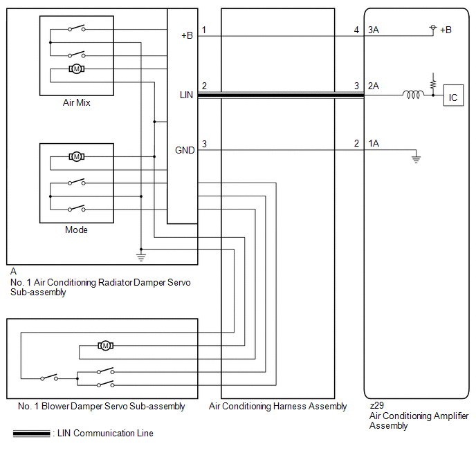
PROCEDURE
| 1. |
PERFORM ACTIVE TEST USING TECHSTREAM |
(a) Disconnect the No. 1 air conditioning radiator damper servo sub-assembly connector.
(b) Connect the Techstream to the DLC3.
(c) Turn the ignition switch to ON.
(d) Turn the Techstream on.
(e) Enter the following menus: Body Electrical / Air Conditioner / Active test.
(f) Perform the Active Test according to the display on the Techstream.
Body Electrical > Air Conditioner > Active Test|
Tester Display | Measurement Item |
Control Range | Diagnostic Note |
|---|---|---|---|
|
Air Mix Servo Targ Pulse(D) |
No. 1 air conditioning radiator damper servo sub-assembly (air mix) pulse |
Min.: 128 Max.: 383 |
Operates between 165 to 257 pulses |
|
Tester Display |
|---|
| Air Mix Servo Targ Pulse(D) |
OK:
The damper servo motor operates smoothly.
| OK | .gif) | REPLACE NO. 1 AIR CONDITIONING RADIATOR DAMPER SERVO SUB-ASSEMBLY
|
.gif)
|
.gif)
| 2. |
INSPECT AIR CONDITIONING HARNESS ASSEMBLY (AIR CONDITIONING AMPLIFIER ASSEMBLY - NO. 1 AIR CONDITIONING RADIATOR DAMPER SERVO SUB-ASSEMBLY) |
(a) Disconnect the z29 air conditioning amplifier assembly connector.
(b) Disconnect the No. 1 air conditioning radiator damper servo sub-assembly connector.
(c) Measure the resistance according to the value(s) in the table below.
Standard Resistance:
|
Tester Connection | Condition |
Specified Condition |
|---|---|---|
|
z29-2 (1A) - A-3 (GND) |
Always | Below 1 ? |
|
z29-3 (2A) - A-2 (LIN) |
Always | Below 1 ? |
|
z29-4 (3A) - A-1 (+B) |
Always | Below 1 ? |
| OK | | REPLACE NO. 1 AIR CONDITIONING RADIATOR DAMPER SERVO SUB-ASSEMBLY
|
| NG | | REPLACE AIR CONDITIONING HARNESS ASSEMBLY
|
READ NEXT:
 Lost Communication with Front Panel LIN (B14B2)
DESCRIPTION The air conditioning control assembly communicates with the air conditioning amplifier assembly via LIN communication.
If a malfunction occurs in the LIN communication system, the air con
Refrigerant Shortage (B14B8)
DESCRIPTION This DTC is stored if the amount of refrigerant in the air conditioning system is insufficient.
The air conditioning amplifier assembly receives the ambient temperature signal, refrigeran
Refrigerant Overabundance Filling Malfunction (B14BD)
DESCRIPTION This DTC is stored if the amount of refrigerant in the in the air conditioning system exceeds a threshold. The air conditioning amplifier assembly judges whether the amount of refrigerant
SEE MORE:
Airbag Signal Signal Plausibility Failure (B15C464)
DESCRIPTION If the DCM (telematics transceiver) detects an error in communication between the DCM (telematics transceiver) and the airbag sensor assembly as a result of the DCM (telematics transceiver) self check, this DTC will be set.
DTC No. Detection Item
DTC Detection Condition Tr
Diagnostic Trouble Code Chart
DIAGNOSTIC TROUBLE CODE CHART Wireless Door Lock Control System
DTC No. Detection Item
Link B1242
Wireless Door Lock Tuner Circuit Malfunction
