Toyota Camry (XV70): Components
COMPONENTS
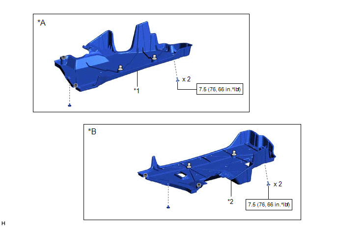
ILLUSTRATION
|
*A | for RH Side |
*B | for LH Side |
|
*1 | NO. 1 FLOOR UNDER COVER |
*2 | NO. 2 FLOOR UNDER COVER |
.png) |
N*m (kgf*cm, ft.*lbf): Specified torque |
- | - |
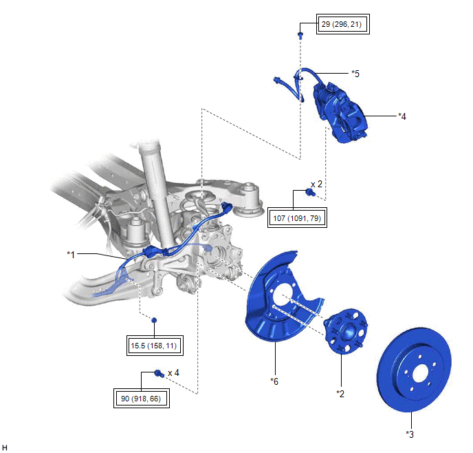
ILLUSTRATION
|
*1 | NO. 2 PARKING BRAKE WIRE ASSEMBLY |
*2 | REAR AXLE HUB AND BEARING ASSEMBLY |
|
*3 | REAR DISC |
*4 | REAR DISC BRAKE CALIPER ASSEMBLY |
|
*5 | REAR FLEXIBLE HOSE |
*6 | REAR DISC BRAKE DUST COVER SUB-ASSEMBLY |
.png) |
Tightening torque for "Major areas involving basic vehicle performance such as moving/turning/stopping": N*m (kgf*cm, ft.*lbf) |
- | - |
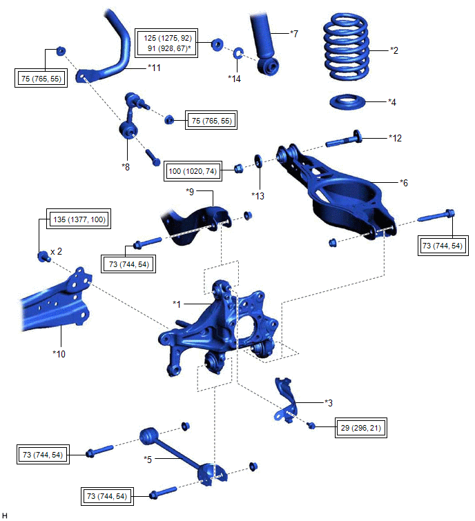
ILLUSTRATION
|
*1 | REAR AXLE CARRIER SUB-ASSEMBLY |
*2 | REAR COIL SPRING |
|
*3 | REAR FLEXIBLE HOSE BRACKET |
*4 | REAR LOWER COIL SPRING INSULATOR |
|
*5 | REAR NO. 1 SUSPENSION ARM ASSEMBLY |
*6 | REAR NO. 2 SUSPENSION ARM ASSEMBLY |
|
*7 | REAR SHOCK ABSORBER ASSEMBLY |
*8 | REAR STABILIZER LINK ASSEMBLY |
|
*9 | REAR UPPER CONTROL ARM ASSEMBLY |
*10 | REAR TRAILING ARM ASSEMBLY |
|
*11 | REAR STABILIZER BAR |
*12 | REAR SUSPENSION TOE ADJUST CAM SUB-ASSEMBLY |
|
*13 | NO. 2 CAMBER ADJUST CAM |
*14 | PLATE WASHER |
|
|
Tightening torque for "Major areas involving basic vehicle performance such as moving/turning/stopping": N*m (kgf*cm, ft.*lbf) |
* | For use with a ball joint lock nut wrench |
READ NEXT:
 Removal
REMOVAL CAUTION / NOTICE / HINT
The necessary procedures (adjustment, calibration, initialization, or registration) that must be performed after parts are removed and installed, or replaced during r
Installation
INSTALLATION CAUTION / NOTICE / HINT
HINT:
Use the same procedure for the RH side and LH side.
The following procedure is for the LH side.
PROCEDURE 1. TEMPORARILY INSTALL REAR AXLE CARR
SEE MORE:
Yaw Rate Sensor Circuit Intermittent (C00631F,C006396,C05201F)
DESCRIPTION The airbag sensor assembly has a built-in yaw rate and acceleration sensor and detects the vehicle condition.
These DTCs are stored when the skid control ECU (brake actuator assembly) receives a malfunction signal from the yaw rate and acceleration sensor (airbag sensor assembly).
Installation
INSTALLATION PROCEDURE 1. INSTALL DOOR CONTROL AND TIRE PRESSURE WARNING ECU AND RECEIVER (w/o Smart Key System)
NOTICE:
Do not drop, strike or otherwise subject the door control and tire pressure warning ECU and receiver to impact.
If the door control and tire pressure warning ECU and receive
