Toyota Camry (XV70): Components
COMPONENTS
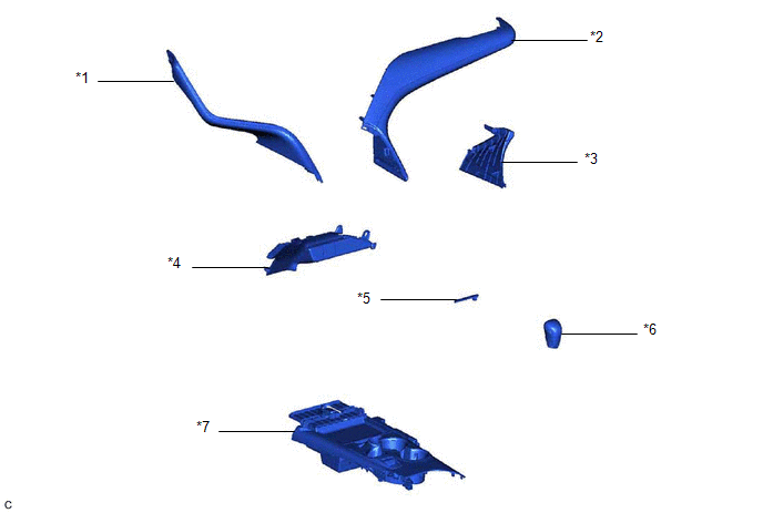
ILLUSTRATION
|
*1 | NO. 1 METER HOOD CLUSTER |
*2 | NO. 2 INSTRUMENT PANEL GARNISH SUB-ASSEMBLY |
|
*3 | INSTRUMENT PANEL FINISH PLATE GARNISH |
*4 | LOWER CENTER INSTRUMENT PANEL FINISH PANEL |
|
*5 | SHIFT LOCK RELEASE BUTTON COVER |
*6 | SHIFT LEVER KNOB SUB-ASSEMBLY |
|
*7 | REAR UPPER CONSOLE PANEL SUB-ASSEMBLY |
- | - |
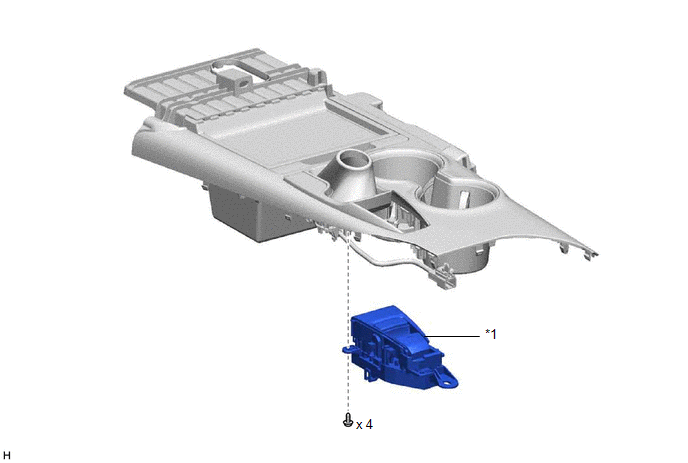
ILLUSTRATION
|
*1 | COMBINATION SWITCH (ELECTRIC PARKING BRAKE SWITCH ASSEMBLY) |
- | - |
READ NEXT:
 Removal
REMOVAL PROCEDURE 1. PRECAUTION
Click here 2. REMOVE NO. 1 METER HOOD CLUSTER
Click here
3. REMOVE NO. 2 INSTRUMENT PANEL GARNISH SUB-ASSEMBLY Click here
4. REMOVE INSTRUMENT PAN
Inspection
INSPECTION PROCEDURE 1. INSPECT COMBINATION SWITCH (ELECTRIC PARKING BRAKE SWITCH ASSEMBLY)
(a) Inspect the NORMAL mode switch:
(1) Measure the resistance according to the value(s) in the tabl
Installation
INSTALLATION PROCEDURE 1. INSTALL COMBINATION SWITCH (ELECTRIC PARKING BRAKE SWITCH ASSEMBLY)
Click here 2. INSTALL REAR UPPER CONSOLE PANEL SUB-ASSEMBLY
Click here
3. INSTALL SHIFT LEVE
SEE MORE:
Components
COMPONENTS ILLUSTRATION
*1 REAR CENTER SEAT OUTER BELT ASSEMBLY
*2 REAR SEAT CUSHION ASSEMBLY
*3 REAR SEAT CUSHION LOCK HOOK
*4 REAR SEAT INNER BELT ASSEMBLY RH
*5 WASHER
- -
Tightening torque for "Major areas involving basic veh
Parts Location
PARTS LOCATION ILLUSTRATION
*1 MAIN BODY ECU (MULTIPLEX NETWORK BODY ECU)
*2 COMBINATION METER ASSEMBLY
*3 DLC3
*4 CERTIFICATION ECU (SMART KEY ECU ASSEMBLY) (w/ Smart Key System)
*5 INSTRUMENT PANEL JUNCTION BLOCK ASSEMBLY
- ECU-B NO. 2 FU
© 2023-2026 Copyright www.tocamry.com
