Toyota Camry (XV70): Components
COMPONENTS
ILLUSTRATION
.png)
|
*1 | REAR ENGINE UNDER COVER LH |
*2 | FRONT FENDER APRON SEAL LH |
|
*3 | NO. 1 ENGINE UNDER COVER |
*4 | FRONT WHEEL OPENING EXTENSION PAD LH |
|
*5 | FRONT WHEEL OPENING EXTENSION PAD RH |
- | - |
.png) |
N*m (kgf*cm, ft.*lbf): Specified torque |
- | - |
ILLUSTRATION
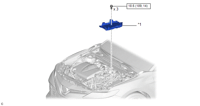
|
*1 | BATTERY CLAMP SUB-ASSEMBLY |
- | - |
|
|
N*m (kgf*cm, ft.*lbf): Specified torque |
- | - |
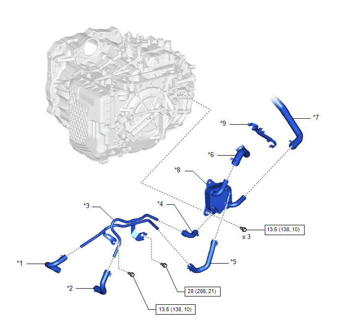
ILLUSTRATION
|
*1 | OUTLET NO. 1 OIL COOLER HOSE |
*2 | INLET NO. 1 OIL COOLER HOSE |
|
*3 | NO. 1 OIL COOLER TUBE SUB-ASSEMBLY WITHOUT HOSE |
*4 | INLET NO. 2 OIL COOLER HOSE |
|
*5 | OUTLET NO. 2 OIL COOLER HOSE |
*6 | NO. 1 WATER BY-PASS HOSE |
|
*7 | WATER BY-PASS HOSE ASSEMBLY |
*8 | TRANSMISSION OIL COOLER |
|
*9 | TRANSMISSION BREATHER CLAMP |
- | - |
|
|
N*m (kgf*cm, ft.*lbf): Specified torque |
- | - |
READ NEXT:
 Removal
REMOVAL CAUTION / NOTICE / HINT
The necessary procedures (adjustment, calibration, initialization or registration) that must be performed after parts are removed and installed, or replaced during tr
Installation
INSTALLATION PROCEDURE 1. INSTALL TRANSMISSION OIL COOLER
(a) Temporarily install the transmission oil cooler to the automatic transaxle case sub-assembly with the bolt (A).
SEE MORE:
Pressure Control Solenoid "B" Circuit Short to Battery (P077512)
DESCRIPTION Changing gears is performed by the ECM turning the solenoid (SL1, SL2, SL3, SL4, SL5 and SL6) valves on and off.
If an open or short occurs in any of the solenoid valve circuits, the ECM controls the remaining normal solenoid valves to allow the vehicle to be driven. If all of the sole
Precaution
PRECAUTION PRECAUTION FOR DISCONNECTING CABLE FROM NEGATIVE BATTERY TERMINAL
NOTICE: When disconnecting the cable from the negative (-) battery terminal, initialize the following systems after the terminal is reconnected.
System Name See Procedure
Lane Tracing Assist System
© 2023-2026 Copyright www.tocamry.com
