Toyota Camry (XV70): Components
COMPONENTS
ILLUSTRATION
|
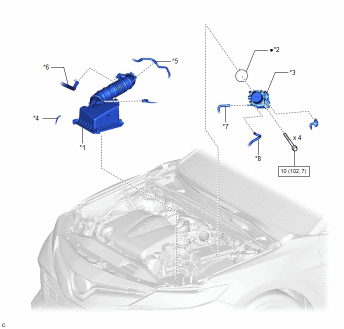
*1 | AIR CLEANER CAP WITH AIR CLEANER HOSE |
*2 | THROTTLE BODY GASKET |
|
*3 | THROTTLE BODY WITH MOTOR ASSEMBLY |
*4 | VACUUM HOSE |
|
*5 | NO. 1 FUEL VAPOR FEED HOSE |
*6 | NO. 2 VENTILATION HOSE |
|
*7 | NO. 2 WATER BY-PASS HOSE |
*8 | NO. 3 WATER BY-PASS HOSE |
.png) |
N*m (kgf*cm, ft.*lbf): Specified torque |
● | Non-reusable part |
READ NEXT:
 On-vehicle Inspection
ON-VEHICLE INSPECTION PROCEDURE
1. INSPECT THROTTLE BODY WITH MOTOR ASSEMBLY (a) Before cleaning, or after cleaning the throttle body with motor assembly and installing it to the vehicle, turn the e
Removal
REMOVAL CAUTION / NOTICE / HINT
The necessary procedures (adjustment, calibration, initialization, or registration) that must be performed after parts are removed and installed, or replaced during t
Inspection
INSPECTION PROCEDURE 1. INSPECT THROTTLE BODY WITH MOTOR ASSEMBLY
(a) Measure the resistance according to the value(s) in the table below.
Standard Resistance:
Tester Connection Con
SEE MORE:
Installation
INSTALLATION PROCEDURE 1. INSTALL VVT SENSOR (for Exhaust Side of Bank 2)
(a) Apply a light coat of engine oil to the O-ring of the VVT sensor. NOTICE:
If reusing the VVT sensor, be sure to inspect the O-ring. (b) Clean the bolt and bolt hole.
(c) Apply adhesive to 2 or 3 threads at the en
Installation
INSTALLATION PROCEDURE 1. INSTALL VACUUM SWITCHING VALVE (for Active Control Engine Mount System)
(a) Install the vacuum switching valve (for active control engine mount system) to the front engine mounting insulator with the nut.
Torque: 6.0 N·m {61 kgf·cm, 53 in·lbf} (b) Connect the 3 vacu
© 2023-2026 Copyright www.tocamry.com
