Toyota Camry (XV70): Electric Parking Brake Switch
Components
COMPONENTS
ILLUSTRATION

|
*1 | ELECTRIC PARKING BRAKE SWITCH ASSEMBLY |
- | - |
Removal
REMOVAL
PROCEDURE
1. PRECAUTION
Click here .gif)
2. REMOVE REAR UPPER CONSOLE PANEL SUB-ASSEMBLY
Click here
3. REMOVE ELECTRIC PARKING BRAKE SWITCH ASSEMBLY
| (a) Disengage the clamp and guide. |
|
.png)
(b) Remove the 4 screws and electric parking brake switch assembly.
Inspection
INSPECTION
PROCEDURE
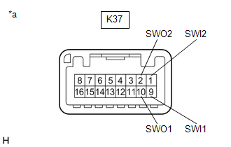
1. INSPECT ELECTRIC PARKING BRAKE SWITCH ASSEMBLY
(a) Check the resistance.
| (1) Measure the resistance according to the value(s) in the table below. Standard Resistance:
If the result is not as specified, replace the electric parking brake switch assembly. |
|
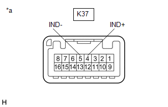
(b) Check the Illuminates.
| (1) Apply battery voltage to the electric parking brake switch assembly and check that the switch illuminates. OK:
If the result is not as specified, replace the electric parking brake switch assembly. |
|
Installation
INSTALLATION
PROCEDURE
1. INSTALL ELECTRIC PARKING BRAKE SWITCH ASSEMBLY
(a) Install the electric parking brake switch assembly with the 4 screws.
(b) Engage the guide and clamp.
2. INSTALL REAR UPPER CONSOLE PANEL SUB-ASSEMBLY
Click here .gif)
READ NEXT:
 Precaution
PRECAUTION PRECAUTION FOR DISCONNECTING CABLE FROM NEGATIVE BATTERY TERMINAL
NOTICE: When disconnecting the cable from the negative (-) battery terminal, initialize the following system(s) after the
Parts Location
PARTS LOCATION ILLUSTRATION
*1 BRAKE ACTUATOR ASSEMBLY
- SKID CONTROL ECU *2
ECM *3
ENGINE ROOM RELAY BLOCK AND JUNCTION BLOCK ASSEMBLY - ABS NO. 2 FUSE
- -
SEE MORE:
GNSS Antenna Circuit Short to Ground (B15C111,B15C113)
DESCRIPTION These DTCs are stored when a malfunction occurs in the telephone and GPS antenna (for Roof Side) circuit.
DTC No. Detection Item
DTC Detection Condition Trouble Area
B15C111 GNSS Antenna Circuit Short to Ground
Current to the GNSS antenna is lower than the
Left Rear Wheel Speed Sensor Circuit Intermittent (C050C1F)
DESCRIPTION Refer to DTC C050C12 Click here
DTC No. Detection Item
DTC Detection Condition Trouble Area
C050C1F Left Rear Wheel Speed Sensor Circuit Intermittent
The speed sensor signal is excessively noisy.
The calculated change in wheel speed is more t
