Toyota Camry (XV70): Parts Location
Toyota Camry Repair Manual XV70 (2018-2024) / Brake / Parking Brake / Electric Parking Brake System / Parts Location
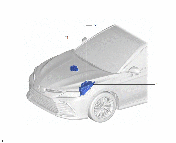
PARTS LOCATION
ILLUSTRATION
|
*1 | BRAKE ACTUATOR ASSEMBLY - SKID CONTROL ECU | *2 |
ECM |
| *3 |
ENGINE ROOM RELAY BLOCK AND JUNCTION BLOCK ASSEMBLY - ABS NO. 2 FUSE |
- | - |
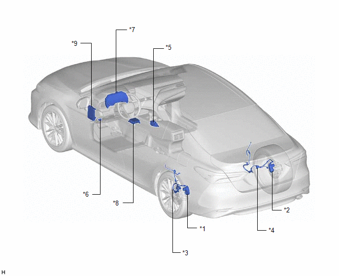
ILLUSTRATION
|
*1 | PARKING BRAKE ACTUATOR ASSEMBLY LH |
*2 | PARKING BRAKE ACTUATOR ASSEMBLY RH |
|
*3 | NO. 2 PARKING BRAKE WIRE ASSEMBLY |
*4 | NO. 1 PARKING BRAKE WIRE ASSEMBLY |
|
*5 | ELECTRIC PARKING BRAKE SWITCH ASSEMBLY |
*6 | DLC3 |
|
*7 | COMBINATION METER ASSEMBLY |
*8 | ACCELERATION SENSOR (AIRBAG SENSOR ASSEMBLY) |
|
*9 | INSTRUMENT PANEL JUNCTION BLOCK ASSEMBLY - ECU-IG1 NO. 2 FUSE - ECU-B NO. 2 FUSE |
- | - |
READ NEXT:
 System Diagram
SYSTEM DIAGRAM
How To Proceed With Troubleshooting
CAUTION / NOTICE / HINT HINT: *: Use the Techstream. PROCEDURE
1.
VEHICLE BROUGHT TO WORKSHOP
NEXT
2.
CUSTOMER PROBLEM ANALYSIS (a) Interview
Problem Symptoms Table
PROBLEM SYMPTOMS TABLE
HINT:
Use the table below to help determine the cause of problem symptoms. If multiple suspected areas are listed, the potential causes of the symptoms are listed in order
SEE MORE:
Components
COMPONENTS ILLUSTRATION
*1 STEERING WHEEL SWITCH HOUSING
*2 TURN SIGNAL SWITCH
*3 WINDSHIELD WIPER SWITCH ASSEMBLY
- -
Front seats
Adjustment procedure
Manual seat
Seat position adjustment lever
Seatback angle adjustment
lever
Vertical height adjustment lever
Power seat
Seat position adjustment switch
Seatback angle adjustment
switch
Seat cushion (front) angle
adjustment switch
Vertical height adju
© 2023-2026 Copyright www.tocamry.com
