Toyota Camry (XV70): System Diagram
Toyota Camry Repair Manual XV70 (2018-2024) / Brake / Parking Brake / Electric Parking Brake System / System Diagram
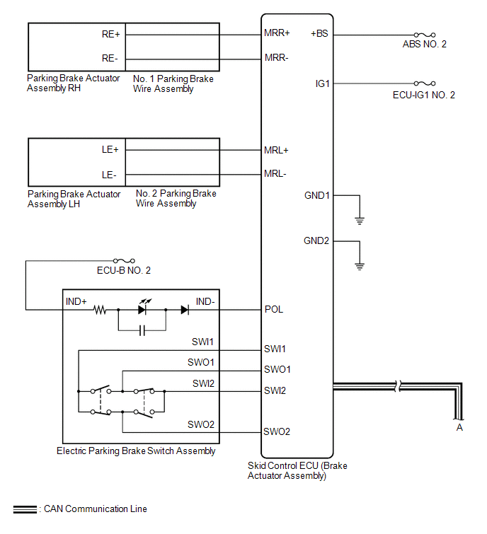
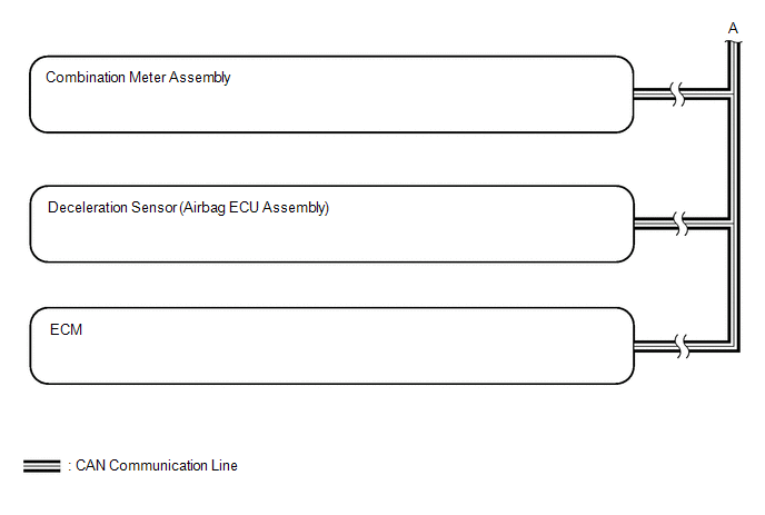
SYSTEM DIAGRAM
READ NEXT:
 How To Proceed With Troubleshooting
CAUTION / NOTICE / HINT HINT: *: Use the Techstream. PROCEDURE
1.
VEHICLE BROUGHT TO WORKSHOP
NEXT
2.
CUSTOMER PROBLEM ANALYSIS (a) Interview
Problem Symptoms Table
PROBLEM SYMPTOMS TABLE
HINT:
Use the table below to help determine the cause of problem symptoms. If multiple suspected areas are listed, the potential causes of the symptoms are listed in order
Terminals Of Ecu
TERMINALS OF ECU CHECK SKID CONTROL ECU (BRAKE ACTUATOR ASSEMBLY)
*a Front view of wire harness connector (to Skid Control ECU (Brake Actuator Assembly))
- -
(a) Disconnect th
SEE MORE:
USB Device Malfunction (B1585)
DESCRIPTION This DTC is stored when a malfunction occurs in a connected device.
DTC No. Detection Item
DTC Detection Condition Trouble Area
B1585 USB Device Malfunction
When any of the following conditions is met:
A non mass-storage class or incompatible proto
Open in Outer Mirror Indicator(Slave) (C1AB5)
DESCRIPTION This DTC is stored when the blind spot monitor sensor LH detects an open in the outer rear view mirror indicator LH.
DTC No. Detection Item
DTC Detection Condition Trouble Area
C1AB5 Open in Outer Mirror Indicator(Slave) Both of the following conditions are met
© 2023-2026 Copyright www.tocamry.com
