Toyota Camry (XV70): Parts Location
PARTS LOCATION
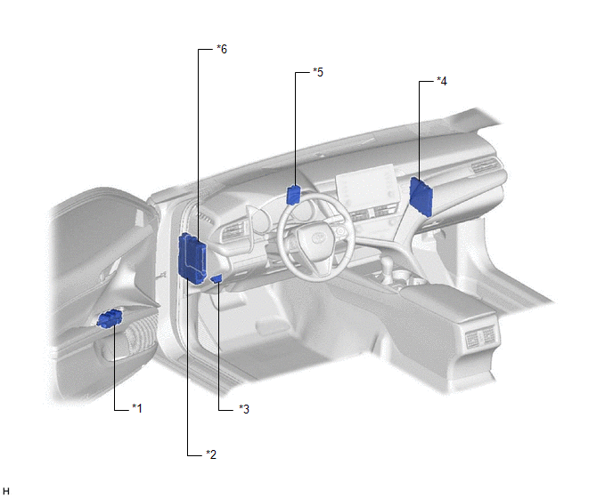
ILLUSTRATION
|
*1 | MULTIPLEX NETWORK MASTER SWITCH ASSEMBLY |
*2 | INSTRUMENT PANEL JUNCTION BLOCK ASSEMBLY - ECU-B NO. 2 FUSE - DOOR F/L FUSE - DOOR F/R FUSE - DOOR R/L FUSE - DOOR R/R FUSE - S/ROOF FUSE (w/ Sliding Roof System or Panoramic Moon Roof System) - STRG LOCK FUSE (w/ Smart Key System) |
|
*3 | DLC3 |
*4 | CERTIFICATION ECU (SMART KEY ECU ASSEMBLY) (w/ Smart Key System) |
|
*5 | ID CODE BOX (IMMOBILISER CODE ECU) (w/ Smart Key System) |
*6 | MAIN BODY ECU (MULTIPLEX NETWORK BODY ECU) |
ILLUSTRATION
|
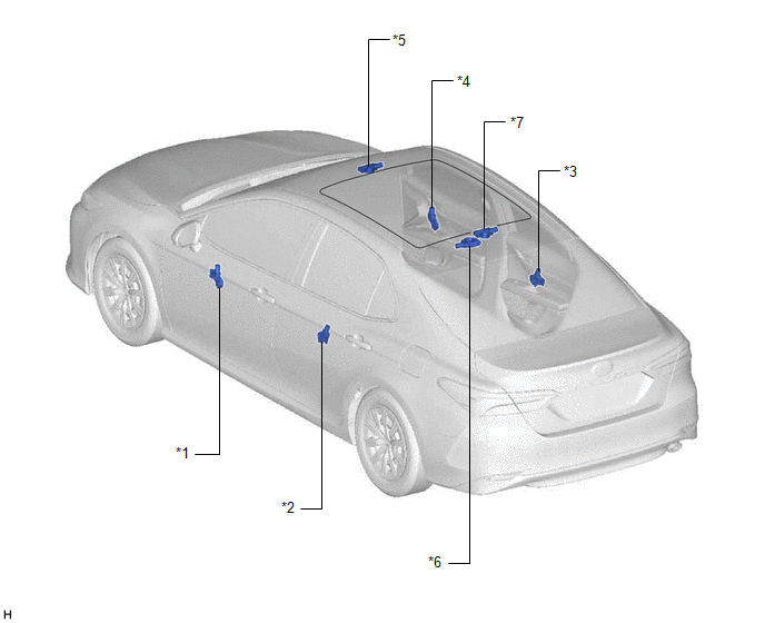
*1 | POWER WINDOW REGULATOR MOTOR ASSEMBLY (for Driver Door) |
*2 | POWER WINDOW REGULATOR MOTOR ASSEMBLY (for Rear Door LH) |
|
*3 | POWER WINDOW REGULATOR MOTOR ASSEMBLY (for Rear Door RH) |
*4 | POWER WINDOW REGULATOR MOTOR ASSEMBLY (for Front Passenger Door) |
|
*5 | SLIDING ROOF ECU (SLIDING ROOF DRIVE GEAR SUB-ASSEMBLY) (w/ Sliding Roof System) |
*6 | SLIDING ROOF ECU (SLIDING ROOF DRIVE GEAR ASSEMBLY) (w/ Panoramic Moon Roof System) |
|
*7 | ROOF SUNSHADE ECU (SLIDING ROOF DRIVE GEAR ASSEMBLY) (w/ Panoramic Moon Roof System) |
- | - |
READ NEXT:
 System Diagram
SYSTEM DIAGRAM DOOR BUS LINES
CERTIFICATION BUS LINES (w/ Smart Key System)
System Description
SYSTEM DESCRIPTION LIN COMMUNICATION SYSTEM DESCRIPTION
The LIN communication system is used for communication between the components in the tables below. If communication cannot be performed throug
How To Proceed With Troubleshooting
CAUTION / NOTICE / HINT
HINT:
Use the following procedure to troubleshoot the LIN communication system.
*: Use the Techstream.
PROCEDURE
1. VEHICLE BROUGHT TO WORKSHOP
SEE MORE:
Parts Location
PARTS LOCATION ILLUSTRATION
*1 GENERATOR ASSEMBLY
*2 ECM
*3 ENGINE ROOM RELAY BLOCK AND JUNCTION BLOCK ASSEMBLY
- - ILLUSTRATION
*1 COMBINATION METER ASSEMBLY
- -
Turn Signal Switch Circuit
DESCRIPTION The steering sensor receives the turn signal switch information and controls the turn signal lights. WIRING DIAGRAM
PROCEDURE
1. READ VALUE USING TECHSTREAM
(a) Connect the Techstream to the DLC3. (b) Turn the ignition switch to ON.
(c) Turn the Techstream on. (
