Toyota Camry (XV70): Components
COMPONENTS
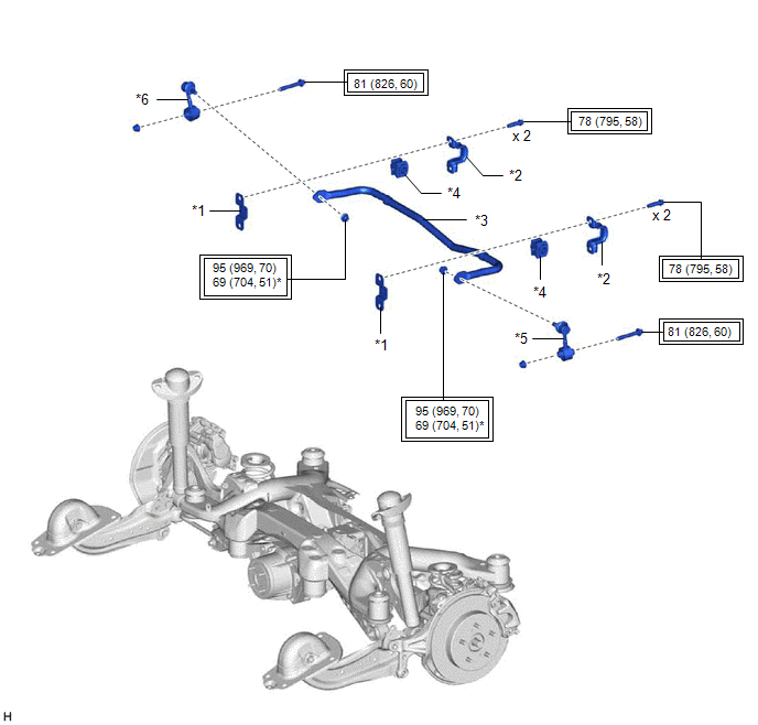
ILLUSTRATION
|
*1 | REAR LOWER STABILIZER BRACKET |
*2 | REAR NO. 1 STABILIZER BAR BRACKET |
|
*3 | REAR STABILIZER BAR |
*4 | REAR STABILIZER BUSHING |
|
*5 | REAR STABILIZER LINK ASSEMBLY LH |
*6 | REAR STABILIZER LINK ASSEMBLY RH |
.png) |
Tightening torque for "Major areas involving basic vehicle performance such as moving/turning/stopping": N*m (kgf*cm, ft.*lbf) |
* | For use with a ball joint lock nut wrench |
READ NEXT:
 Removal
REMOVAL CAUTION / NOTICE / HINT
The necessary procedures (adjustment, calibration, initialization, or registration) that must be performed after parts are removed and installed, or replaced during r
Inspection
INSPECTION PROCEDURE 1. INSPECT REAR STABILIZER LINK ASSEMBLY
(a) Inspect the turning torque of the ball joint.
(1) Secure the rear stabilizer link assembly in a vise using aluminum plates.
NOT
Installation
INSTALLATION PROCEDURE 1. INSTALL REAR STABILIZER BUSHING
(a) Install the 2 rear stabilizer bushings to the outside of the stoppers on the rear stabilizer bar.
NOTICE: Be sure to install the
SEE MORE:
Recommended fluids and lubricants
Fluids and lubricants
*1: For additional information, see “engine oil recommendation”.
*2: As an alternative to this recommended oil, sae 5w-30 conventional
petroleum based oil may be used and meet all specifications
and requirements necessary to maintain the new vehicle limited
Installation
INSTALLATION PROCEDURE 1. INSTALL CAMSHAFT TIMING GEAR BOLT
(a) Make sure that the No. 1 cylinder is at TDC/compression. HINT:
Check that the cutout of the camshaft timing gear assembly is at the top and align the timing mark (cutout) of the crankshaft pulley with the timing mark on the timing c
© 2023-2026 Copyright www.tocamry.com
