Toyota Camry (XV70): Removal
REMOVAL
CAUTION / NOTICE / HINT
The necessary procedures (adjustment, calibration, initialization, or registration) that must be performed after parts are removed and installed, or replaced during rear stabilizer bar removal/installation are shown below.
Necessary Procedures After Parts Removed/Installed/Replaced|
Replaced Part or Performed Procedure |
Necessary Procedure | Effect/Inoperative Function when Necessary Procedure not Performed |
Link |
|---|---|---|---|
| Inspection After Repair |
|
|
CAUTION:
To prevent burns, do not touch the engine, exhaust pipe or other high temperature components while the engine is hot.
.png)
PROCEDURE
1. REMOVE REAR WHEEL
Click here .gif)
2. REMOVE CENTER EXHAUST PIPE ASSEMBLY
Click here
3. REMOVE REAR STABILIZER LINK ASSEMBLY LH
| (a) Loosen the nut (A) of the rear stabilizer link assembly LH. HINT: If the ball joint turns together with the nut, use a 6 mm hexagon socket wrench to hold the stud bolt. |
|
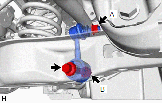
(b) Loosen the bolt of the rear stabilizer link assembly LH.
NOTICE:
Because the nut (B) has its own stopper, do not turn the nut (B). Loosen the bolt with the nut (B) secured.
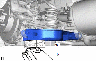
| (c) Using a jack and a wooden block, support the rear No. 2 suspension arm assembly. NOTICE:
|
|
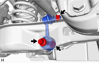
| (d) Remove the bolt, 2 nuts and rear stabilizer link assembly LH. |
|
4. REMOVE REAR STABILIZER LINK ASSEMBLY RH
HINT:
Perform the same procedure as for the LH side.
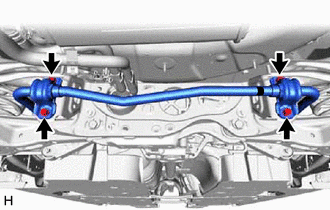
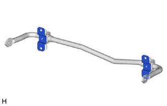
5. REMOVE REAR STABILIZER BAR
| (a) Remove the 4 bolts, rear stabilizer bar, 2 rear No. 1 stabilizer bar brackets, 2 rear stabilizer bushings, 2 rear lower stabilizer brackets from the rear suspension member sub-assembly. |
|
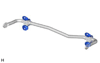
6. REMOVE REAR LOWER STABILIZER BRACKET
| (a) Remove the 2 rear lower stabilizer brackets from the rear stabilizer bushing. |
|
7. REMOVE REAR NO. 1 STABILIZER BAR BRACKET
| (a) Remove the 2 rear No. 1 stabilizer bar brackets from the 2 rear stabilizer bushings. |
|
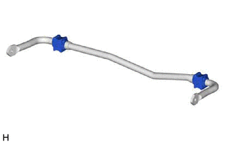
8. REMOVE REAR STABILIZER BUSHING
| (a) Remove the 2 rear stabilizer bushings from the rear stabilizer bar. |
|
READ NEXT:
 Inspection
INSPECTION PROCEDURE 1. INSPECT REAR STABILIZER LINK ASSEMBLY
(a) Inspect the turning torque of the ball joint.
(1) Secure the rear stabilizer link assembly in a vise using aluminum plates.
NOT
Installation
INSTALLATION PROCEDURE 1. INSTALL REAR STABILIZER BUSHING
(a) Install the 2 rear stabilizer bushings to the outside of the stoppers on the rear stabilizer bar.
NOTICE: Be sure to install the
SEE MORE:
Electric Parking Brake Actuator (C13B800)
DESCRIPTION
DTC No. Detection Item
DTC Detection Condition Trouble Area
Memory Note
C13B800 Electric Parking Brake Actuator
Diagnosis Condition:
Electric parking brake operating
Malfunction Status:
Free spinning or repeated slipping is detected
Black Screen
PROCEDURE
1. CHECK DISPLAY SETTING
(a) Check that the display is not in screen off mode. OK: The display setting is not in screen off mode.
NG
CHANGE SCREEN TO SCREEN ON MODE
OK
2.
CHECK IMAGE QUALITY SETTING (a) Check that the
