Toyota Camry (XV70): Disassembly
DISASSEMBLY
PROCEDURE
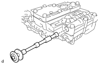
1. REMOVE MANUAL VALVE
| (a) Remove the manual valve from the transmission valve body assembly. |
|
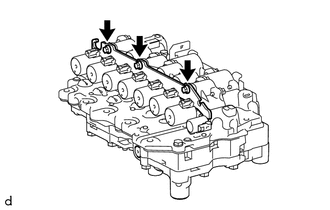
2. REMOVE SOLENOID LOCK PLATE
| (a) Remove the 3 bolts and solenoid lock plate from the transmission valve body assembly. |
|
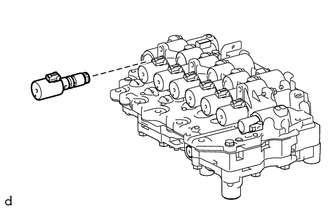
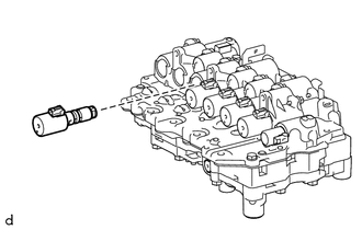
3. REMOVE SOLENOID (SLU) VALVE
| (a) Remove the solenoid (SLU) valve from the transmission valve body assembly. |
|
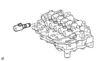
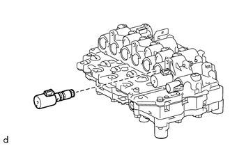
4. REMOVE SOLENOID (SL5) VALVE
| (a) Remove the solenoid (SL5) valve from the transmission valve body assembly. |
|
5. REMOVE SOLENOID (SL6) VALVE
| (a) Remove the solenoid (SL6) valve from the transmission valve body assembly. |
|
6. REMOVE SOLENOID (SL4) VALVE
| (a) Remove the solenoid (SL4) valve from the transmission valve body assembly. |
|
7. REMOVE SOLENOID (SL3) VALVE
| (a) Remove the solenoid (SL3) valve from the transmission valve body assembly. |
|
8. REMOVE SOLENOID (SL1) VALVE
| (a) Remove the solenoid (SL1) valve from the transmission valve body assembly. |
|
9. REMOVE SOLENOID (SL2) VALVE
| (a) Remove the solenoid (SL2) valve from the transmission valve body assembly. |
|
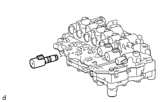
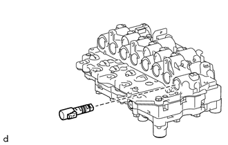
10. REMOVE SOLENOID (SLT) VALVE
| (a) Remove the solenoid (SLT) valve from the transmission valve body assembly. |
|
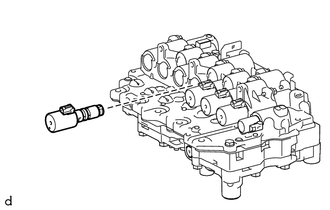
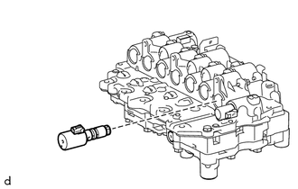
11. REMOVE SOLENOID (SL) VALVE
| (a) Remove the bolt and solenoid (SL) valve from the transmission valve body assembly. |
|
READ NEXT:
 Inspection
INSPECTION PROCEDURE 1. INSPECT SOLENOID (SL) VALVE
(a) Measure the resistance according to the value(s) in the table below.
Standard Resistance:
Tester Connection Condition
S
Reassembly
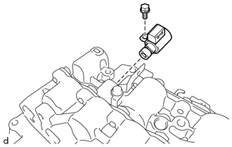
REASSEMBLY PROCEDURE 1. INSTALL SOLENOID (SL) VALVE
(a) Coat the solenoid (SL) valve with Toyota Genuine ATF WS.
(b) Install the solenoid (SL) valve to the transmission valv
Installation
INSTALLATION PROCEDURE 1. INSTALL TRANSMISSION VALVE BODY ASSEMBLY
(a) Coat 2 new transaxle case gaskets with Toyota Genuine ATF WS and install them to the automatic transaxle case sub-assembly.
(
SEE MORE:
Slip Indicator Light Remains ON
DESCRIPTION This procedure is for troubleshooting when the slip indicator light remains on but no DTCs are output.
The skid control ECU (brake actuator assembly) controls the slip indicator light in the combination meter assembly via CAN communication.
The slip indicator light blinks during VSC
Low Pressure Fuel System Pressure - Too High (P008B00)
DESCRIPTION Refer to DTC P008A00. Click here
DTC No. Detection Item
DTC Detection Condition Trouble Area
MIL Memory
Note P008B00
Low Pressure Fuel System Pressure - Too High
Actual fuel pressure (for low pressure side) value higher than target fuel pres
