
Toyota Camry (XV70): Disassembly
DISASSEMBLY
PROCEDURE
1. REMOVE METER MIRROR WIRE
| (a) Disconnect the connector. |
|
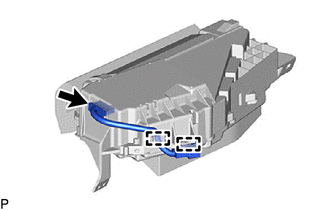
(b) Disengage the 2 clamps to remove the meter mirror wire.
2. REMOVE NO. 1 COMBINATION SPEED METER CUSHION
(a) Remove the No. 1 combination speed meter cushion.
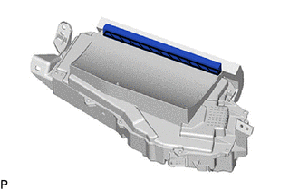
 |
Double-sided Tape |
3. REMOVE COMBINATION SPEED METER CUSHION
(a) Remove the combination speed meter cushion.
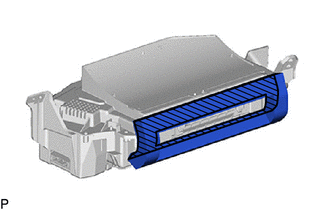
|
|
Double-sided Tape |
4. REMOVE NO. 1 COMBINATION METER MIRROR PLATE
| (a) Remove the 8 screws. |
|
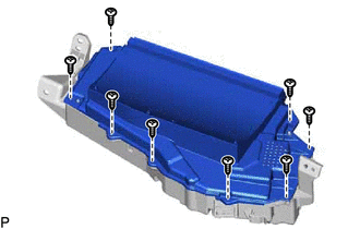
(b) Disengage the 2 claws as shown in the illustration.
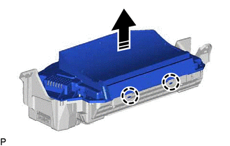
 |
Remove in this Direction |
| (c) Remove the screw. |
|
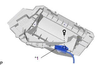
(d) Disconnect the light sensor assembly to remove the No. 1 combination meter mirror plate.
READ NEXT:
SEE MORE:
 Disassembly
DISASSEMBLY CAUTION / NOTICE / HINT
NOTICE: w/ Smart Key System with Steering Lock Actuator Assembly:
Before replacing the steering lock actuator assembly, refer to Registration.
Click here
PROCEDURE
1. REMOVE UPPER STEERING COLUMN BRACKET WITH SWITCH ASSEMBLY (w/o Smart Key Sy
Diagnostic Trouble Code Chart
DIAGNOSTIC TROUBLE CODE CHART Dynamic Radar Cruise Control System
DTC No. Detection Item
DTC Output from Link
P057113 Brake Switch "A" Circuit Open
Cruise Control
P057162 Brake Switch "A" Signal Compare Failure
Cruise Control
P
© 2023-2026 Copyright www.tocamry.com
