Toyota Camry (XV70): Disassembly
DISASSEMBLY
CAUTION / NOTICE / HINT
NOTICE:
w/ Smart Key System with Steering Lock Actuator Assembly:
Before replacing the steering lock actuator assembly, refer to Registration.
Click here .gif)
PROCEDURE
1. REMOVE UPPER STEERING COLUMN BRACKET WITH SWITCH ASSEMBLY (w/o Smart Key System)
(a) Secure the steering column assembly in a vise between aluminum plates.
NOTICE:
Do not overtighten the vise.
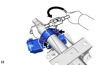
(b) Using a drill, drill a hole in the 2 steering lock set bolts and insert a screw extractor.
| (c) Using the screw extractor, remove the 2 steering lock set bolts, upper steering column clamp and upper steering column bracket with switch assembly. |
|
2. REMOVE STEERING LOCK ACTUATOR ASSEMBLY (w/ Smart Key System with Steering Lock Actuator Assembly)
HINT:
Perform the same procedure as for the upper steering column bracket with switch assembly (w/o Smart Key System).
3. REMOVE IGNITION SWITCH LOCK CYLINDER ASSEMBLY (w/o Smart Key System)
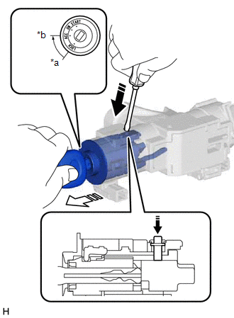
(a) Turn the ignition switch to ACC.
|
*a | LOCK |
|
*b | ACC |
.png) |
Push |
 |
Pull |
(b) Insert the tip of a screwdriver into the hole in the upper steering column bracket assembly, as shown in the illustration, and pull out the ignition switch lock cylinder assembly.
4. REMOVE UN-LOCK WARNING SWITCH ASSEMBLY (w/o Smart Key System)
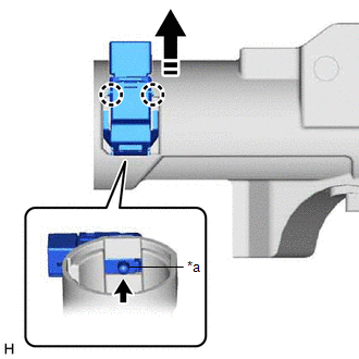
| (a) Remove the un-lock warning switch assembly by pushing up the center part and releasing the 2 claws. HINT: Slide the un-lock warning switch assembly in the direction shown by the arrow in the illustration to remove it. |
|
5. REMOVE IGNITION OR STARTER SWITCH ASSEMBLY (w/o Smart Key System)
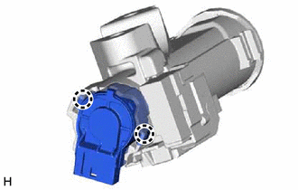
| (a) Disengage the 2 claws and remove the ignition or starter switch assembly from the upper steering column bracket assembly. |
|
READ NEXT:
 Inspection
INSPECTION PROCEDURE 1. INSPECT STEERING COLUMN ASSEMBLY
(a) Check that the 2 bushings are securely installed to the steering column assembly.
If the bushings are deformed, missing or damag
Reassembly
REASSEMBLY PROCEDURE 1. INSTALL IGNITION OR STARTER SWITCH ASSEMBLY (w/o Smart Key System)
(a) Engage the 2 claws to install the ignition or starter switch assembly onto the upper steering column b
Installation
INSTALLATION PROCEDURE 1. ALIGN FRONT WHEELS FACING STRAIGHT AHEAD
2. INSTALL STEERING COLUMN ASSEMBLY NOTICE: Make sure that the wire harness is not interfering with the steering column assembly.
SEE MORE:
Reassembly
REASSEMBLY CAUTION / NOTICE / HINT
HINT: Perform the removal and installation of the front disc brake piston, cylinder boot and piston seal one side at a time. PROCEDURE
1. TEMPORARILY TIGHTEN FRONT DISC BRAKE BLEEDER PLUG (a) Temporarily install the front disc brake bleeder plug to the front di
Terminals Of Ecu
TERMINALS OF ECU TERMINALS OF ECU
*a Component without harness connected
(Skid Control ECU (Brake Actuator Assembly))
- -
HINT:
As a waterproof connector is used for the brake actuator assembly, voltage and waveform inspections cannot be performed with the connector c
