Toyota Camry (XV70): Reassembly
REASSEMBLY
PROCEDURE
1. INSTALL IGNITION OR STARTER SWITCH ASSEMBLY (w/o Smart Key System)
(a) Engage the 2 claws to install the ignition or starter switch assembly onto the upper steering column bracket assembly.
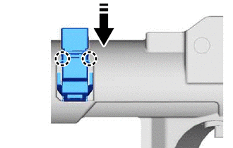
2. INSTALL UN-LOCK WARNING SWITCH ASSEMBLY (w/o Smart Key System)
| (a) Engage the 2 claws to install the un-lock warning switch assembly to the upper steering column bracket assembly. HINT: Slide the un-lock warning switch assembly, in the direction shown by the arrow in the illustration, to install it. |
|
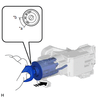
3. INSTALL IGNITION SWITCH LOCK CYLINDER ASSEMBLY (w/o Smart Key System)
| (a) Turn the ignition switch to ACC. |
|
(b) Install the ignition switch lock cylinder assembly to the upper steering column bracket assembly.
(c) Make sure that the ignition switch lock cylinder assembly is securely installed into the upper steering column bracket assembly.
4. INSTALL UPPER STEERING COLUMN BRACKET WITH SWITCH ASSEMBLY (w/o Smart Key System)
(a) Secure the steering column assembly in a vise between aluminum plates.
NOTICE:
Do not overtighten the vise.
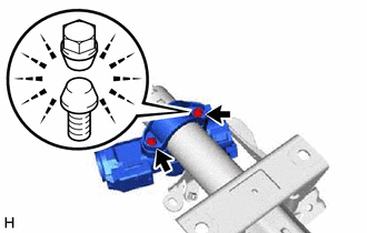
(b) Temporarily install the upper steering column bracket with switch assembly and upper steering column clamp with 2 new steering lock set bolts.
| (c) Tighten the 2 steering lock set bolts until the bolt head breaks off. |
|
5. INSTALL STEERING LOCK ACTUATOR ASSEMBLY (w/ Smart Key System with Steering Lock Actuator Assembly)
NOTICE:
When replacing the steering lock actuator assembly, perform registration.
Click here .gif)
HINT:
Perform the same procedure as for the upper steering column bracket with switch assembly (w/o Smart Key System).
READ NEXT:
 Installation
INSTALLATION PROCEDURE 1. ALIGN FRONT WHEELS FACING STRAIGHT AHEAD
2. INSTALL STEERING COLUMN ASSEMBLY NOTICE: Make sure that the wire harness is not interfering with the steering column assembly.
Components
COMPONENTS ILLUSTRATION
*1 COWL SIDE TRIM SUB-ASSEMBLY LH
*2 FRONT DOOR OPENING TRIM WEATHERSTRIP LH
*3 FRONT DOOR SCUFF PLATE LH
*4 HOOD LOCK CONTROL LEVER
SEE MORE:
Parts Location
PARTS LOCATION ILLUSTRATION
*1 BRAKE ACTUATOR ASSEMBLY
*2 FORWARD RECOGNITION CAMERA
(w/ Front Camera System)
*3 ECM (for A25A-FKS)
*4 ECM (for 2GR-FKS)
*5 RACK AND PINION POWER STEERING GEAR ASSEMBLY
*6 MILLIMETER WAVE RADAR SENSOR ASSEMBLY
Head restraints
Head restraints are provided for all seats.
Adjustable type
Up
Pull the head restraint up.
Down
Push the head restraint down while
pressing the lock release button.
Integrated type
Head restraints cannot be adjusted or removed.
■Removing the head restraints
Pull the head restr
