Toyota Camry (XV70): Components
Toyota Camry Repair Manual XV70 (2018-2024) / Steering / Steering Column / Steering Heater Switch / Components
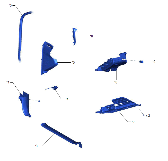
COMPONENTS
ILLUSTRATION
|
*1 | COWL SIDE TRIM SUB-ASSEMBLY LH |
*2 | FRONT DOOR OPENING TRIM WEATHERSTRIP LH |
|
*3 | FRONT DOOR SCUFF PLATE LH |
*4 | HOOD LOCK CONTROL LEVER SUB-ASSEMBLY |
|
*5 | INSTRUMENT SIDE PANEL LH |
*6 | NO. 1 INSTRUMENT PANEL SUB-ASSEMBLY |
|
*7 | NO. 1 INSTRUMENT PANEL UNDER COVER SUB-ASSEMBLY |
*8 | NO. 2 METER HOOD CLUSTER |
|
*9 | STEERING HEATER SWITCH |
- | - |
READ NEXT:
 Removal
REMOVAL PROCEDURE 1. REMOVE FRONT DOOR SCUFF PLATE LH
Click here
2. REMOVE COWL SIDE TRIM SUB-ASSEMBLY LH
Click here
3. DISCONNECT FRONT DOOR OPENING TRIM WEATHERSTRIP LH
Inspection
INSPECTION PROCEDURE 1. INSPECT STEERING HEATER SWITCH
(a) Remove the steering heater switch. Click here
*a Component without harness connected
(St
Installation
INSTALLATION PROCEDURE 1. INSTALL STEERING HEATER SWITCH
(a) Engage the 2 claws to install the steering heater switch as shown in the illustration.
Install in this Direction
SEE MORE:
Windshield wipers and
washer
Operating the wiper lever
Operating the lever operates the
wipers or washer as follows.
When intermittent windshield wiper operation is selected, the wiper
interval can be also adjusted.
*1 or
*2
Intermittent windshield
wiper operation
The intermittent windshield
wiper operat
Components
COMPONENTS ILLUSTRATION
*A for TMC made
- -
*1 NO. 1 ENGINE UNDER COVER
*2 NO. 2 ENGINE UNDER COVER ASSEMBLY
*3 FRONT WHEEL OPENING EXTENSION PAD LH
*4 FRONT WHEEL OPENING EXTENSION PAD RH
*5 FRONT FENDER APRON SEAL LH
- -
© 2023-2026 Copyright www.tocamry.com
