
Toyota Camry (XV70): Removal
REMOVAL
PROCEDURE
1. REMOVE FRONT DOOR SCUFF PLATE LH
Click here .gif)
2. REMOVE COWL SIDE TRIM SUB-ASSEMBLY LH
Click here
3. DISCONNECT FRONT DOOR OPENING TRIM WEATHERSTRIP LH
Click here
4. REMOVE INSTRUMENT SIDE PANEL LH
Click here
5. REMOVE NO. 1 INSTRUMENT PANEL UNDER COVER SUB-ASSEMBLY
Click here
6. REMOVE NO. 2 METER HOOD CLUSTER
Click here
7. DISCONNECT HOOD LOCK CONTROL LEVER SUB-ASSEMBLY
Click here
8. REMOVE NO. 1 INSTRUMENT PANEL SUB-ASSEMBLY
Click here
9. REMOVE STEERING HEATER SWITCH
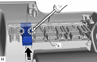
(a) Using a screwdriver with its tip wrapped with protective tape, disengage the 2 claws and remove the steering heater switch as shown in the illustration.
|
*a | Protective Tape |
.png) |
Remove in this Direction |
READ NEXT:
 Inspection
INSPECTION PROCEDURE 1. INSPECT STEERING HEATER SWITCH
(a) Remove the steering heater switch. Click here
*a Component without harness connected
(St
Installation
INSTALLATION PROCEDURE 1. INSTALL STEERING HEATER SWITCH
(a) Engage the 2 claws to install the steering heater switch as shown in the illustration.
Install in this Direction
SEE MORE:
Terminals Of Ecu
TERMINALS OF ECU HINT: Check from the rear of the connector while it is connected to the components.
RADIO AND DISPLAY RECEIVER ASSEMBLY
Terminal No. (Symbol) Wiring Color
Terminal Description Condition
Specified Condition
K4-1 (FR+) - K3-1 (GND1)
LA-LG - BR*1
Voice Recognition Microphone Disconnected (B1579)
DESCRIPTION The radio and display receiver assembly, roof console box sub-assembly and telephone microphone assembly are connected to each other using the microphone connection detection signal lines.
This DTC is stored when a microphone connection detection signal line is disconnected.
DTC
© 2023-2026 Copyright www.tocamry.com
