Toyota Camry (XV70): Front Passenger Side Power Window Switch
Components
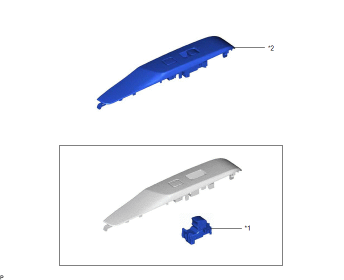
COMPONENTS
ILLUSTRATION
|
*1 | POWER WINDOW REGULATOR SWITCH ASSEMBLY |
*2 | POWER WINDOW REGULATOR SWITCH ASSEMBLY WITH FRONT DOOR UPPER ARMREST BASE PANEL |
Removal
REMOVAL
PROCEDURE
1. REMOVE POWER WINDOW REGULATOR SWITCH ASSEMBLY WITH FRONT DOOR UPPER ARMREST BASE PANEL
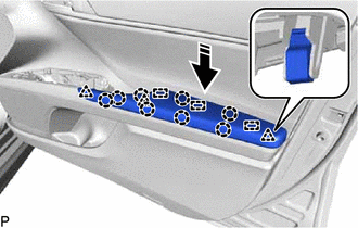
(a) Apply protective tape to the front door trim board sub-assembly as shown in the illustration.
.png)
.png) |
Protective Tape |
(b) Disengage the 3 clips, 15 claws and 8 guides as shown in the illustration.
.png)
.png) |
Place Hand Here |
.png) |
Remove in this Direction |
.png) |
Order of Removal |
(c) Disengage the guide as shown in the illustration.
.png)
|
|
Remove in this Direction |
(d) Disconnect the connector to remove the power window regulator switch assembly with front door upper armrest base panel.
(e) Engage the 3 clips, 8 claws and 3 guides to install the front armrest assembly as shown in the illustration.
|
|
Install in this Direction |
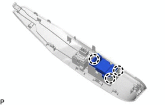
2. REMOVE POWER WINDOW REGULATOR SWITCH ASSEMBLY
| (a) Disengage the 3 claws to remove the power window regulator switch assembly. |
|
Inspection
INSPECTION
PROCEDURE
1. INSPECT POWER WINDOW REGULATOR SWITCH ASSEMBLY
| (a) Check the switch function. (1) Measure the resistance according to the value(s) in the table below. Standard Resistance:
If the result is not as specified, replace the power window regulator switch assembly. |
|
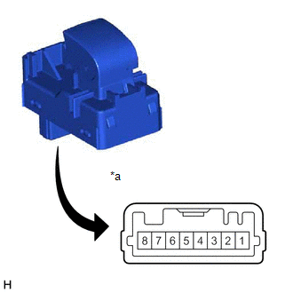
(b) Check that the LED illuminates.
(1) Apply battery voltage to the power window regulator switch assembly and check that the LED illuminates.
OK:
|
Battery Connection | Specified Condition |
|---|---|
|
Battery positive (+) → 3 Battery negative (-) → 1 |
LED illuminates |
If the result is not as specified, replace the power window regulator switch assembly.
Installation
INSTALLATION
PROCEDURE
1. INSTALL POWER WINDOW REGULATOR SWITCH ASSEMBLY
(a) Engage the 3 claws to install the power window regulator switch assembly.
2. INSTALL POWER WINDOW REGULATOR SWITCH ASSEMBLY WITH FRONT DOOR UPPER ARMREST BASE PANEL
Click here .gif)
READ NEXT:
 Precaution
PRECAUTION PRECAUTION FOR DISCONNECTING CABLE FROM NEGATIVE BATTERY TERMINAL
NOTICE: When disconnecting the cable from the negative (-) battery terminal, initialize the following systems after the
Parts Location
PARTS LOCATION ILLUSTRATION
*1 MAIN BODY ECU (MULTIPLEX NETWORK BODY ECU)
*2 COMBINATION METER ASSEMBLY
*3 DLC3
*4 CERTIFICATION ECU (SMART KEY ECU ASSEMBLY
SEE MORE:
Left Front Wheel Speed Sensor Circuit Short to Ground or Open (C050014)
DESCRIPTION Refer to DTC C050012 Click here
DTC No. Detection Item
DTC Detection Condition Trouble Area
C050014 Left Front Wheel Speed Sensor Circuit Short to Ground or Open
A short or open circuit is detected in the speed sensor signal circuit for 0.12 seconds or
Front Brake Flexible Hose
ComponentsCOMPONENTS ILLUSTRATION
*1 FRONT FLEXIBLE HOSE
*2 GASKET
*3 BRAKE LINE
*4 FRONT SPEED SENSOR
*5 UNION BOLT
- -
Tightening torque for "Major areas involving basic vehicle performance such as moving/turning/stopping" : N*
