Toyota Camry (XV70): Reassembly
REASSEMBLY
CAUTION / NOTICE / HINT
NOTICE:
- As imbalance affects vibration and noise performance, make sure to ensure correct angular alignment of the following components during installation.
- PROPELLER INTERMEDIATE SHAFT ASSEMBLY
- REAR PROPELLER SHAFT ASSEMBLY
- LARGE DIAMETER PROPELLER SHAFT BOOT CLAMP
- SMALL DIAMETER PROPELLER SHAFT BOOT CLAMP
- BALL CAGE, INNER RACE
- When using a vise, place aluminum plates between the part and vise.
- When using a vise, do not overtighten it.
PROCEDURE
1. INSTALL CENTER SUPPORT BEARING
| (a) Using SST and a plastic hammer, install a new No. 1 dust deflector to the dimension (A). SST: 09710-18050 09711-01090 Dimension (A): 17.2 to 17.6 mm (0.678 to 0.692 in.) NOTICE: Do not excessively press the No. 1 dust deflector. |
|
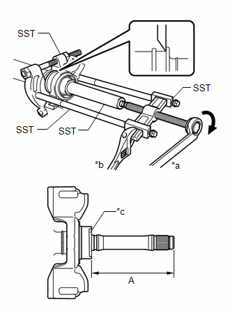
| (b) Using SST, install a new center support bearing and flange to the propeller intermediate shaft assembly to the dimension (A). SST: 09612-22011 SST: 09950-00020 SST: 09950-00040 SST: 09950-40011 09951-04020 09952-04010 09953-04020 09954-04040 09957-04010 Dimension (A): 113.5 mm (4.47 in.) HINT: Perform this procedure with 2 or more people and prevent the propeller shaft from rotating. |
|
2. INSTALL UNIVERSAL BOOT KIT
| (a) Install each new parts to the propeller intermediate shaft assembly in the order shown in the illustration. |
|
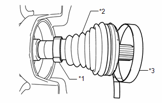
(b) Install the small diameter side of the propeller shaft boot to the propeller intermediate shaft assembly.
| (c) Align the matchmarks placed before removal. |
|
(d) Using a brass bar and a hammer, install the inner race to the propeller intermediate shaft assembly.
NOTICE:
Be careful not to damage the inner race.
| (e) Using a snap ring expander, install a new propeller shaft snap ring to the propeller intermediate shaft assembly. |
|
| (f) Align the matchmarks and install the ball cage to the inner race. |
|
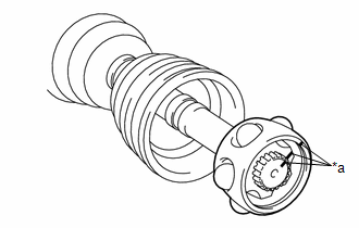
(g) Install the 6 balls with grease to the inner race.
NOTICE:
Be careful not to drop the balls.
HINT:
Apply grease to the balls to keep them from falling.
3. INSTALL REAR PROPELLER SHAFT ASSEMBLY
| (a) Align the matchmarks and insert the propeller intermediate shaft assembly into the rear propeller shaft assembly. |
|
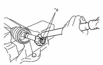
| (b) Align the crimp position of the small diameter propeller shaft boot clamp with the matchmark of the rear propeller shaft assembly. |
|
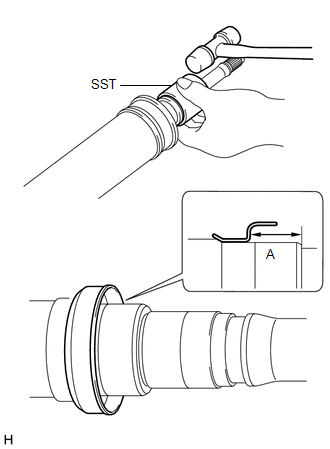
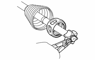
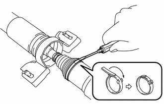
| (c) Place SST onto the small diameter propeller shaft boot clamp, and while pushing it against the propeller shaft boot, slightly tighten the bolt of SST. SST: 09521-24010 |
|
(d) While holding SST, tighten the bolt of SST until the specified clearance value of the small diameter propeller shaft boot clamp is met.
Clearance:
Below 0.8 mm (0.0315 in.)
(e) Remove SST.
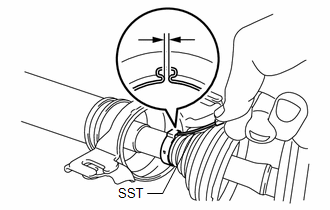
| (f) Using SST, measure the clearance shown in the illustration. SST: 09240-00021 Clearance: Below 0.8 mm (0.0315 in.) NOTICE: If the clearance is not as specified, retighten SST. |
|
(g) Fill the rear propeller shaft assembly and propeller shaft boot with grease.
Standard Grease Capacity:
90 to 100 g (3.18 to 3.52 oz)
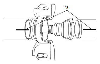
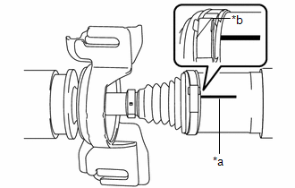
| (h) Install the propeller shaft boot to the rear propeller shaft assembly to the specified value (A). |
|
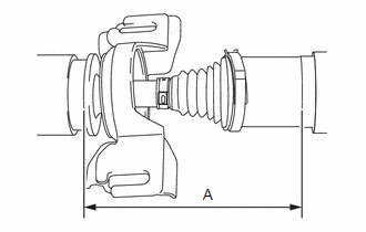
(i) Measure the distance (A) of the propeller shaft assembly shown in the illustration. If the value is not as specified, reinstall the propeller shaft boot.
Dimension (A):
189.3 to 191.7 mm (7.45 to 7.55 in.)
| (j) Align the crimp position of the large diameter propeller shaft boot clamp with the matchmark of the rear propeller shaft assembly. |
|
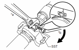
| (k) Temporarily bend the lever from the fulcrum part of the large diameter propeller shaft boot clamp. |
|
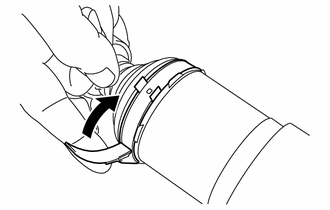
| (l) Using a screwdriver, stake the large diameter propeller shaft boot clamp. NOTICE: Be careful not to damage the propeller shaft boot. |
|
| (m) Confirm that the matchmarks of the propeller intermediate shaft assembly and rear propeller shaft assembly are aligned. |
|
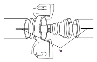
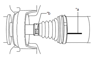
| (n) Check whether the propeller intermediate shaft assembly dimension (A) is within specification. Dimension (A): 189.3 to 191.7 mm (7.45 to 7.55 in.) |
|
READ NEXT:
 Installation
INSTALLATION PROCEDURE 1. TEMPORARILY TIGHTEN PROPELLER WITH CENTER BEARING SHAFT ASSEMBLY
(a) When reusing a propeller with center bearing shaft assembly and rear differential carrier assembly:
Propeller Shaft System
Problem Symptoms TablePROBLEM SYMPTOMS TABLE
HINT: Use the table below to help determine the cause of problem symptoms. If multiple suspected areas are listed, the potential causes of the symptoms a
SEE MORE:
Control Module Communication Bus "B" Off Bus Off (U007488,...,U015187)
DESCRIPTION The skid control ECU (brake actuator assembly) communicates with the following ECUs and sensors via CAN communication.
ECM
TCM (ECM)
Yaw rate and acceleration sensor (airbag sensor assembly)
Steering angle sensor
Power steering ECU (rack and pinion power steering gea
Installation
INSTALLATION PROCEDURE 1. INSTALL FUEL SENDER GAUGE ASSEMBLY
(a) Engage the claw to install the fuel sender gauge assembly to the fuel suction tube with pump and gauge assembly.
NOTICE: Be careful not to bend the arm of the fuel sender gauge assembly.
(b) Engage the 2 clamps to connect the wir
