Toyota Camry (XV70): Installation
INSTALLATION
PROCEDURE
1. TEMPORARILY TIGHTEN PROPELLER WITH CENTER BEARING SHAFT ASSEMBLY
| (a) When reusing a propeller with center bearing shaft assembly and rear differential carrier assembly: (1) Align the matchmarks on the rear differential carrier assembly and propeller with center bearing shaft assembly. (2) Temporarily install the 4 nuts and 4 washers. NOTICE: Do not apply grease to the 4 bolts, 4 nuts or 4 washers. |
|
.png)
| (b) When using a new propeller with center bearing shaft assembly or rear differential carrier assembly: (1) Align the alignment marks on the rear differential carrier assembly and propeller with center bearing shaft assembly. (2) Temporarily install the 4 nuts and 4 washers. NOTICE: Do not apply grease to the 4 bolts, 4 nuts or 4 washers. |
|
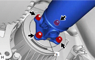
| (c) Align the matchmarks on the transfer assembly and propeller with center bearing shaft assembly. |
|
.png)
(d) Temporarily install the 4 nuts and 4 washers.
NOTICE:
Do not apply grease to the 4 bolts, 4 nuts or 4 washers.
| (e) Temporarily install the propeller with center bearing shaft assembly with the 2 bolts and 2 center No. 2 support bearing washers (for front side). NOTICE:
|
|
.png)
| (f) Temporarily install the propeller with center bearing shaft assembly with the 2 bolts and 2 center No. 2 support bearing washers (for rear side). NOTICE:
|
|
.png)
| (g) Fully tighten the 4 nuts. Torque: 35 N |
READ NEXT:
 Propeller Shaft System
Problem Symptoms TablePROBLEM SYMPTOMS TABLE
HINT: Use the table below to help determine the cause of problem symptoms. If multiple suspected areas are listed, the potential causes of the symptoms a
Components
COMPONENTS ILLUSTRATION
*1 REAR DRIVE SHAFT ASSEMBLY LH
*2 REAR DRIVE SHAFT INBOARD JOINT SHAFT SNAP RING LH
*3 REAR DIFFERENTIAL CARRIER ASSEMBLY
- -
SEE MORE:
Touch Panel Switch does not Function
CAUTION / NOTICE / HINT
NOTICE:
Depending on the parts that are replaced during vehicle inspection or maintenance, performing initialization, registration or calibration may be needed. Refer to Precaution for Navigation System.
Click here
When replacing the radio and display receiver
Terminals Of Ecu
TERMINALS OF ECU
NOTICE:
DTCs may be output when connectors are disconnected during inspection. Therefore, be sure to clear the DTCs using the Techstream once the inspection has been completed.
Do not apply excessive force to the forward recognition camera connector.
*A Be
