Toyota Camry (XV70): Parts Location
PARTS LOCATION
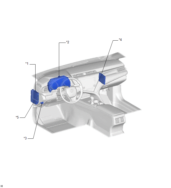
ILLUSTRATION
|
*1 | MAIN BODY ECU (MULTIPLEX NETWORK BODY ECU) |
*2 | COMBINATION METER ASSEMBLY |
|
*3 | DLC3 |
*4 | CERTIFICATION ECU (SMART KEY ECU ASSEMBLY) (w/ Smart Key System) |
|
*5 | INSTRUMENT PANEL JUNCTION BLOCK ASSEMBLY - ECU-B NO. 2 FUSE - DOOR F/L FUSE - DOOR F/R FUSE - DOOR R/L FUSE - DOOR R/R FUSE |
- | - |
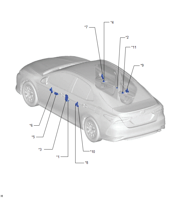
ILLUSTRATION
|
*1 | FRONT DOOR COURTESY LIGHT SWITCH ASSEMBLY (for LH) |
*2 | FRONT DOOR COURTESY LIGHT SWITCH ASSEMBLY (for RH) |
|
*3 | FRONT DOOR LOCK WITH MOTOR ASSEMBLY LH |
*4 | POWER WINDOW REGULATOR SWITCH ASSEMBLY |
|
*5 | MULTIPLEX NETWORK MASTER SWITCH ASSEMBLY |
*6 | POWER WINDOW REGULATOR MOTOR ASSEMBLY (for Driver Door) |
|
*7 | POWER WINDOW REGULATOR MOTOR ASSEMBLY (for Front Passenger Door) |
*8 | POWER WINDOW REGULATOR MOTOR ASSEMBLY (for Rear LH Door) |
|
*9 | POWER WINDOW REGULATOR MOTOR ASSEMBLY (for Rear RH Door) |
*10 | REAR POWER WINDOW REGULATOR SWITCH ASSEMBLY (for LH Door) |
|
*11 | REAR POWER WINDOW REGULATOR SWITCH ASSEMBLY (for RH Door) |
- | - |
READ NEXT:
 System Diagram
SYSTEM DIAGRAM
Communication Table
Transmitting ECU Receiving ECU
Signal Communication Method
Multiplex Network Master Switch Assembly
Power Window Regulat
System Description
SYSTEM DESCRIPTION POWER WINDOW CONTROL SYSTEM DESCRIPTION
(a) The power window control system controls the power window operation using the power window regulator motor assemblies. The main contro
How To Proceed With Troubleshooting
CAUTION / NOTICE / HINT
HINT:
Use the following procedure to troubleshoot the power window control system.
*: Use the Techstream.
PROCEDURE
1. VEHICLE BROUGHT TO WORKSHO
SEE MORE:
Components
COMPONENTS ILLUSTRATION
*1 NO. 1 METER HOOD CLUSTER
*2 NO. 2 INSTRUMENT PANEL GARNISH SUB-ASSEMBLY
*3 INSTRUMENT PANEL FINISH PLATE GARNISH
*4 LOWER CENTER INSTRUMENT PANEL FINISH PANEL
*5 SHIFT LOCK RELEASE BUTTON COVER
*6 SHIFT LEVER KNOB SUB
Slip Indicator Light Remains ON
DESCRIPTION This procedure is for troubleshooting when the slip indicator light remains on but no DTCs are output.
The skid control ECU (brake actuator assembly) controls the slip indicator light in the combination meter assembly via CAN communication.
The slip indicator light blinks during VSC
