Toyota Camry (XV70): Front Pillar Upper Cover
Components
COMPONENTS
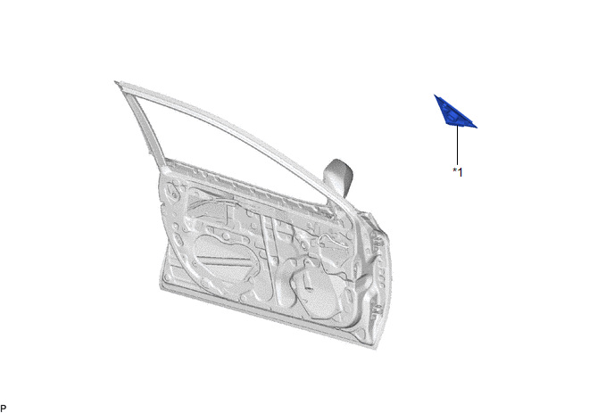
ILLUSTRATION
|
*1 | FRONT DOOR FRONT LOWER FRAME UPPER COVER |
- | - |
Removal
REMOVAL
CAUTION / NOTICE / HINT
The necessary procedures (adjustment, calibration, initialization or registration) that must be performed after parts are removed and installed, or replaced during front pillar upper cover removal/installation are shown below.
Necessary Procedure After Parts Removed/Installed/Replaced|
Replaced Part or Performed Procedure |
Necessary Procedure | Effect/Inoperative Function when Necessary Procedure not Performed |
Link |
|---|---|---|---|
|
Disconnect cable from negative battery terminal |
Perform steering sensor zero point calibration |
Lane Tracing Assist System |
|
|
Pre-collision System | |||
|
Memorize steering angle neutral point |
Parking Assist Monitor System |
| |
|
Panoramic View Monitor System |
| ||
|
Front door glass sub-assembly | Initialize power window control system |
|
|
HINT:
- Use the same procedure for the RH side and LH side.
- The following procedure is for the LH side.
PROCEDURE
1. REMOVE FRONT DOOR BELT MOULDING ASSEMBLY
Click here .gif)
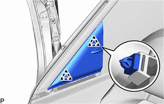
2. REMOVE FRONT DOOR FRONT LOWER FRAME UPPER COVER
| (a) Disengage the 2 clips to remove the front door front lower frame upper cover. |
|
Installation
INSTALLATION
CAUTION / NOTICE / HINT
HINT:
- Use the same procedure for the RH side and LH side.
- The following procedure is for the LH side.
PROCEDURE
1. INSTALL FRONT DOOR FRONT LOWER FRAME UPPER COVER
(a) Engage the 2 clips to install the front door front lower frame upper cover.
2. INSTALL FRONT DOOR BELT MOULDING ASSEMBLY
Click here
.gif)
READ NEXT:
 Components
COMPONENTS ILLUSTRATION
*1 LUGGAGE COMPARTMENT DOOR OUTSIDE GARNISH PROTECTOR
*2 LUGGAGE COMPARTMENT DOOR OUTSIDE GARNISH SUB-ASSEMBLY
*3 NO. 2 LUGGAGE COMPARTMENT D
Removal
REMOVAL PROCEDURE 1. REMOVE REAR LIGHT ASSEMBLY LH
Click here
2. REMOVE REAR LIGHT ASSEMBLY RH
HINT: Use the same procedure as for the LH side. 3. REMOVE NO. 3 LUGGAGE COMPARTMENT DOOR OUT
SEE MORE:
Shift Paddle Switch Circuit
DESCRIPTION Moving the shift lever to S enables the shift range to be selected. The shift range can be selected by operating the "+" or "-" shift paddle switch. WIRING DIAGRAM
CAUTION / NOTICE / HINT
NOTICE: After turning the engine switch off, waiting time may be required before disconnecting
Problem Symptoms Table
PROBLEM SYMPTOMS TABLE HINT: Use the table below to help determine the cause of problem symptoms. If multiple suspected areas are listed, the potential causes of the symptoms are listed in order of probability in the "Suspected Area" column of the table. Check each symptom by checking the suspected
