Toyota Camry (XV70): GPS Antenna Connection Malfunction(short) (B15C0,B15C1)
DESCRIPTION
These DTCs are stored when a malfunction occurs in the navigation antenna assembly.
|
DTC No. | Detection Item |
DTC Detection Condition | Trouble Area |
|---|---|---|---|
|
B15C0 | GPS Antenna Connection Malfunction(short) |
Navigation antenna malfunction |
|
| B15C1 |
GPS Antenna Connection Malfunction(break) |
Navigation antenna power source malfunction |
|
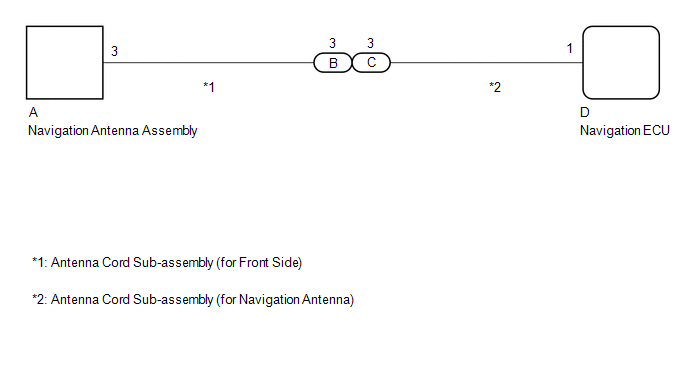
WIRING DIAGRAM
CAUTION / NOTICE / HINT
NOTICE:
- When replacing the navigation ECU, always replace it with a new one. If a navigation ECU which was installed to another vehicle is used, the following may occur:
- A communication malfunction DTC may be stored.
- The navigation ECU may not operate normally.
PROCEDURE
|
1. | CHECK DTC |
(a) Clear the DTCs.
Body Electrical > Navigation System > Clear DTCs(b) Recheck for DTCs and check that no DTCs are output.
Body Electrical > Navigation System > Trouble CodesOK:
No DTCs are output.
| OK | .gif) |
USE SIMULATION METHOD TO CHECK |
|
.gif)
| 2. |
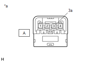
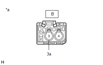
INSPECT ANTENNA CORD SUB-ASSEMBLY (for Front Side) |
(a) Remove the antenna cord sub-assembly (for Front Side).
Click here
.gif)
(b) Measure the resistance according to the value(s) in the table below.
Standard Resistance:
|
Tester Connection | Condition |
Specified Condition |
|---|---|---|
|
A-3 - B-3 | Always |
Below 1 Ω |
|
A-3a - B-3a | Always |
Below 1 Ω |
|
A-3 or B-3 - Body ground |
Always | 10 kΩ or higher |
|
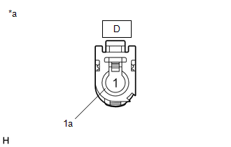
*a | Component without harness connected (Antenna Cord Sub-assembly (for Front Side)) |
|
*a | Component without harness connected (Antenna Cord Sub-assembly (for Front Side)) |
| NG | | REPLACE ANTENNA CORD SUB-ASSEMBLY (for Front Side) |
|
| 3. |
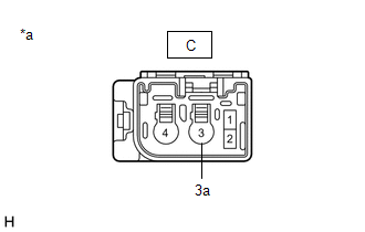
INSPECT ANTENNA CORD SUB-ASSEMBLY (for Navigation Antenna) |
(a) Remove the antenna cord sub-assembly (for Navigation Antenna).
Click here
(b) Measure the resistance according to the value(s) in the table below.
Standard Resistance:
|
Tester Connection | Condition |
Specified Condition |
|---|---|---|
|
C-3 - D-1 | Always |
Below 1 Ω |
|
C-3a - D-1a | Always |
Below 1 Ω |
|
C-3 or D-1 - Body ground |
Always | 10 kΩ or higher |
|
*a | Component without harness connected (Antenna Cord Sub-assembly (for Navigation Antenna)) |
|
*a | Component without harness connected (Antenna Cord Sub-assembly (for Navigation Antenna)) |
| NG | | REPLACE ANTENNA CORD SUB-ASSEMBLY (for Navigation Antenna) |
|
| 4. |
INSPECT NAVIGATION ANTENNA ASSEMBLY |
(a) Remove the navigation antenna assembly.
Click here
(b) Inspect the navigation antenna assembly.
Click here
| OK | | REPLACE NAVIGATION ECU |
| NG | | REPLACE NAVIGATION ANTENNA ASSEMBLY |
READ NEXT:
 Speed Signal Malfunction (B15C2)
DESCRIPTION The navigation ECU receives a vehicle speed signal from the combination meter assembly and information from the navigation antenna assembly, and then adjusts the vehicle position on the ma
Speaker Output Short (B15C3)
DESCRIPTION This DTC is stored when a malfunction occurs in the speakers.
DTC No. Detection Item
DTC Detection Condition Trouble Area
B15C3 Speaker Output Short
A short
Stereo Component Amplifier Disconnected (B15D3)
DESCRIPTION The radio and display receiver assembly and stereo component amplifier assembly are connected by the AVC-LAN communication line.
DTC No. Detection Item
DTC Detection Condition
SEE MORE:
Inspection
INSPECTION PROCEDURE 1. INSPECT TRANSMISSION OIL CLEANER MAGNET
(a) Use the removed transmission oil cleaner magnets to collect any steel chips. Examine the chips and particles in the transaxle housing and on the transmission oil cleaner magnets to determine what type of wear might be found in
Pressure Control Solenoid "D" Circuit Short to Battery (P271312)
DESCRIPTION Refer to DTC P27137F. Click here
DTC No. Detection Item
DTC Detection Condition Trouble Area
MIL Memory
Note P271312
Pressure Control Solenoid "D" Circuit Short to Battery
While the engine is running, a short to +B is detected in the soleno
