Toyota Camry (XV70): Inspection
INSPECTION
PROCEDURE
1. INSPECT FUEL PRESSURE SENSOR (FUEL DELIVERY PIPE WITH SENSOR ASSEMBLY)
NOTICE:
- Do not remove the fuel pressure sensor from the fuel delivery pipe with sensor assembly.
- If the fuel pressure sensor is removed, replace the fuel pressure sensor (fuel delivery pipe with sensor assembly) with a new one.
(a) Check the fuel pressure sensor output voltage.
| (1) Apply 5 V between terminals 1 (VC) and 3 (E2). NOTICE:
HINT: If a stable power supply is not available, connect 4 nickel-metal hydride batteries (1.2 V each) or equivalent in series. |
|
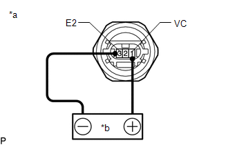
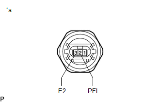
| (2) Measure the voltage according to the value(s) in the table below. Standard Voltage:
*: The output voltage changes depending on the voltage applied to the terminals. If the result is not as specified, replace the fuel pressure sensor (fuel delivery pipe with sensor assembly). |
|
READ NEXT:
 Installation
INSTALLATION PROCEDURE 1. INSTALL FUEL PRESSURE SENSOR (FUEL DELIVERY PIPE WITH SENSOR ASSEMBLY)
HINT: Perform "Inspection After Repair" after replacing the fuel pressure sensor (fuel delivery pipe
Components
COMPONENTS ILLUSTRATION
*A w/ Dust Cap
- -
*1 FUEL PRESSURE SENSOR (FUEL DELIVERY PIPE WITH SENSOR ASSEMBLY LH)
*2 FUEL PIPE PLUG SUB-ASSEMBLY
*3 DUST C
SEE MORE:
Initialization
INITIALIZATION INITIALIZE POWER WINDOW CONTROL SYSTEM (ALL DOORS)
NOTICE:
When a door window regulator sub-assembly, power window regulator motor assembly, door glass or door glass run is reinstalled or replaced, the power window control system must be initialized. Functions such as the aut
On-vehicle Inspection
ON-VEHICLE INSPECTION PROCEDURE
1. REMOVE FRONT WHEEL OPENING EXTENSION PAD RH Click here
2. REMOVE FRONT WHEEL OPENING EXTENSION PAD LH
Click here
3. REMOVE NO. 1 ENGINE UNDER COVER Click here
4. REMOVE NO. 2 ENGINE UNDER COVER ASSEMBLY
Click here
5. CHECK TRAN
