
Toyota Camry (XV70): Inspection
INSPECTION
PROCEDURE
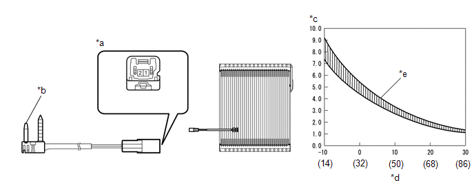
1. INSPECT NO. 1 COOLER THERMISTOR
(a) Measure the resistance according to the value(s) in the table below.
|
*a | Component without harness connected (No. 1 Cooler Thermistor) |
*b | Sensing Portion |
|
*c | Resistance (k?) |
*d | Temperature (°C (°F)) |
|
*e | Allowable Range |
- | - |
Standard Resistance:
|
Tester Connection | Condition |
Specified Condition |
|---|---|---|
|
1 - 2 | -10°C (14°F) |
7.30 to 9.10 k? |
|
-5°C (23°F) | 5.65 to 6.95 k? | |
|
0°C (32°F) | 4.40 to 5.35 k? | |
|
5°C (41°F) | 3.40 to 4.15 k? | |
|
10°C (50°F) | 2.70 to 3.25 k? | |
|
15°C (59°F) | 2.14 to 2.58 k? | |
|
20°C (68°F) | 1.71 to 2.05 k? | |
|
25°C (77°F) | 1.38 to 1.64 k? | |
|
30°C (86°F) | 1.11 to 1.32 k? |
If the resistance is not as specified, replace the No. 1 cooler thermistor.
NOTICE:
- Hold the sensor only by its connector. Touching the sensing portion may change the resistance value.
- When measuring, the sensor temperature must be the same as the ambient temperature.
HINT:
As the temperature increases, the resistance decreases (see the graph).
READ NEXT:
SEE MORE:
 Parts Location
PARTS LOCATION ILLUSTRATION
*A w/ Forward Recognition Camera
*B w/ Smart Key System
*C w/o Smart Key System
*D w/ Drive Mode Switch
*1 FORWARD RECOGNITION CAMERA
*2 BRAKE ACTUATOR ASSEMBLY
- SKID CONTROL ECU
*3 ECM
*4 RACK
Installation
INSTALLATION PROCEDURE 1. INSTALL REAR SUSPENSION MEMBER FRONT BODY MOUNTING CUSHION (for LH Side)
(a) Confirm the installation direction and temporarily install a new rear suspension member front body mounting cushion.
NOTICE:
Position the rear suspension member front body mounting cushion
© 2023-2026 Copyright www.tocamry.com
