Toyota Camry (XV70): 2gr-fks Coolant
Components
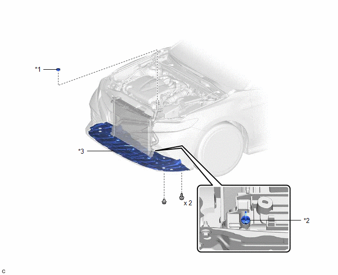
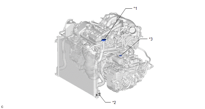
COMPONENTS
ILLUSTRATION
|
*1 | RADIATOR CAP SUB-ASSEMBLY |
*2 | RADIATOR DRAIN COCK PLUG |
|
*3 | NO. 1 ENGINE UNDER COVER |
- | - |
Replacement
REPLACEMENT
CAUTION / NOTICE / HINT
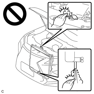
CAUTION:
Do not remove the radiator cap sub-assembly, cylinder block drain cock plug or radiator drain cock plug while the engine and radiator assembly are still hot. Pressurized, hot engine coolant and steam may be released and cause serious burns.
PROCEDURE
1. DRAIN ENGINE COOLANT
CAUTION:
Do not remove the radiator cap sub-assembly, cylinder block drain cock plug or radiator drain cock plug while the engine and radiator assembly are still hot. Pressurized, hot engine coolant and steam may be released and cause serious burns.
| (a) Remove the 2 screws and clip. |
|
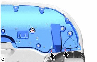
(b) Pull down the No. 1 engine under cover.
NOTICE:
Do not damage the No. 1 engine under cover.
| (c) Connect a hose with an inside diameter of 8.3 mm (0.327 in.) to the radiator drain cock as shown in the illustration. |
|
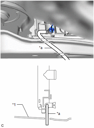
(d) Loosen the radiator drain cock plug.
|
*1 | Radiator Cap Sub-assembly |
*2 | Radiator Drain Cock Plug |
|
*3 | Cylinder Block Drain Cock Plug |
- | - |
(e) Loosen the cylinder block drain cock plug.
(f) Remove the radiator cap sub-assembly. Then drain the engine coolant.
HINT:
Collect the engine coolant in a container and dispose of it according to the regulations in your area.
(g) Tighten the radiator drain cock plug by hand.
(h) Tighten the cylinder block drain cock plug.
Torque:
12.7 N
READ NEXT:
 2gr-fks Drive Belt
ComponentsCOMPONENTS ILLUSTRATION
*1 FRONT FENDER APRON SEAL RH
*2 V-RIBBED BELT RemovalREMOVAL PROCEDURE
1. REMOVE FRONT WHEEL RH Click here
2. REMOVE FRONT FENDER APRON
Components
COMPONENTS ILLUSTRATION
*1 FRONT WHEEL OPENING EXTENSION PAD LH
*2 FRONT WHEEL OPENING EXTENSION PAD RH
*3 NO. 1 ENGINE UNDER COVER
*4 REAR ENGINE UNDER COVER RH
SEE MORE:
Precaution
PRECAUTION IGNITION SWITCH EXPRESSION HINT:
The type of ignition switch used on this model differs depending on the specifications of the vehicle. The expressions listed in the table below are used in this section.
Expression Ignition Switch (Position)
Engine Switch (Condition)
Problem Symptoms Table
PROBLEM SYMPTOMS TABLE
HINT:
Use the table below to help determine the cause of problem symptoms. If multiple suspected areas are listed, the potential causes of the symptoms are listed in order of probability in the "Suspected Area" column of the table. Check each symptom by checking the susp
