
Toyota Camry (XV70): Components
Toyota Camry Repair Manual XV70 (2018-2024) / General / Maintenance / 2gr-fks Oil And Oil Filter / Components
COMPONENTS
ILLUSTRATION
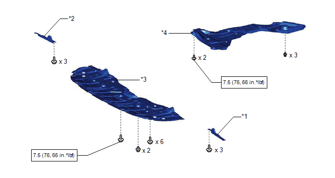
|
*1 | FRONT WHEEL OPENING EXTENSION PAD LH |
*2 | FRONT WHEEL OPENING EXTENSION PAD RH |
|
*3 | NO. 1 ENGINE UNDER COVER |
*4 | REAR ENGINE UNDER COVER RH |
.png) |
N*m (kgf*cm, ft.*lbf): Specified torque |
- | - |
ILLUSTRATION
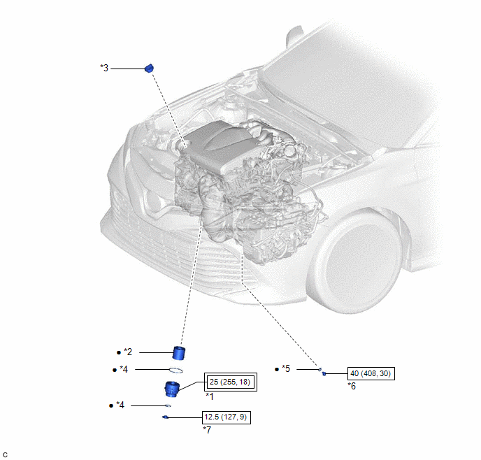
|
*1 | OIL FILTER CAP ASSEMBLY |
*2 | OIL FILTER ELEMENT |
|
*3 | OIL FILLER CAP SUB-ASSEMBLY |
*4 | O-RING |
|
*5 | GASKET |
*6 | OIL PAN DRAIN PLUG |
|
*7 | OIL FILTER DRAIN PLUG |
- | - |
.png) |
Tightening torque for "Major areas involving basic vehicle performance such as moving/turning/stopping": N*m (kgf*cm, ft.*lbf) |
|
N*m (kgf*cm, ft.*lbf): Specified torque |
|
● | Non-reusable part |
- | - |
READ NEXT:
 Replacement
REPLACEMENT CAUTION / NOTICE / HINT
CAUTION:
Prolonged and repeated contact with engine oil will result in the removal of natural oils from the skin, leading to dryness, irritation and dermatiti
2gr-fks Spark Plug
ComponentsCOMPONENTS ILLUSTRATION
*1 IGNITION COIL ASSEMBLY
*2 SPARK PLUG
*3 V-BANK COVER SUB-ASSEMBLY
*4 VACUUM HOSE
N*m (kgf*cm, ft.*lbf): Specif
A25a-fks Air Cleaner Filter Element
ComponentsCOMPONENTS ILLUSTRATION
*1 AIR CLEANER CAP SUB-ASSEMBLY
*2 AIR CLEANER FILTER ELEMENT SUB-ASSEMBLY RemovalREMOVAL PROCEDURE
1. SEPARATE AIR CLEANER CAP SUB-ASSEMBLY
SEE MORE:
Target Adjustment(sequential Recognition)
TARGET ADJUSTMENT(SEQUENTIAL RECOGNITION) CAUTION / NOTICE / HINT
NOTICE: Make sure to read "Before Starting Target Adjustment" before proceeding with work.
Click here PROCEDURE
1. SECURE APPROPRIATE AREA FOR PERFORMING LEARNING
(a) Park the vehicle on a level surface.
HINT:
M
Seat belts
Make sure that all occupants are wearing their seat belts before
driving the vehicle.
Correct use of the seat belts
Extend the shoulder belt so that
it comes fully over the shoulder,
but does not come into contact
with the neck or slide off the
shoulder.
Position the lap belt as low
© 2023-2026 Copyright www.tocamry.com
