Toyota Camry (XV70): Steering Pad Switch Circuit
DESCRIPTION
- The steering pad switch assembly outputs the on/off signal and various control signals to the ECM.
- The ECM performs cruise control according to the signals received from the steering pad switch assembly.
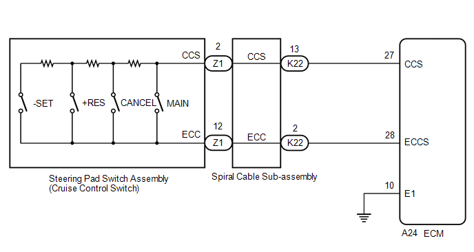
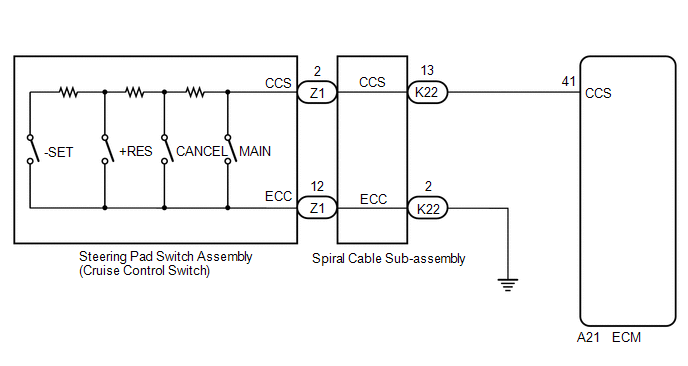
WIRING DIAGRAM
for A25A-FKS
for 2GR-FKS
CAUTION / NOTICE / HINT
NOTICE:
- The vehicle is equipped with a Supplemental Restraint System (SRS) which includes components such as airbags. Before servicing (including removal or installation of parts), be sure to read the precaution for Supplemental Restraint System.
Click here
.gif)
- Before replacing the ECM, refer to Registration.
w/ Smart Key System: Click here
w/o Smart Key System: Click here
PROCEDURE
|
1. | READ VALUE USING TECHSTREAM (Radar Cruise1) |
(a) Read the Data List according to the display on the Techstream.
Powertrain > Cruise Control > Data List|
Tester Display | Measurement Item |
Range | Normal Condition |
Diagnostic Note |
|---|---|---|---|---|
|
Cancel Switch | CANCEL switch status |
ON or OFF | ON: CANCEL switch on OFF: CANCEL switch off |
- |
| -SET Switch |
-SET switch status | ON or OFF |
ON: -SET switch on OFF: -SET switch off |
- |
| +RES Switch |
+RES switch status | ON or OFF |
ON: +RES switch on OFF: +RES switch off |
- |
| Cruise Main Switch Operation Condition |
Cruise control main switch status |
ON or OFF | ON: Cruise control main switch pushed OFF: Cruise control main switch not pushed |
- |
|
Tester Display |
|---|
| Cancel Switch |
|
-SET Switch |
| +RES Switch |
|
Cruise Main Switch Operation Condition |
OK:
The value of each Data List item changes according to the operation of the steering pad switch assembly.
| OK | .gif) | PROCEED TO NEXT SUSPECTED AREA SHOWN IN PROBLEM SYMPTOMS TABLE |
|
.gif)
| 2. |
INSPECT STEERING PAD SWITCH ASSEMBLY |
Click here
| NG | | REPLACE STEERING PAD SWITCH ASSEMBLY |
|
| 3. |
INSPECT SPIRAL CABLE SUB-ASSEMBLY |
Click here
| NG | | REPLACE SPIRAL CABLE SUB-ASSEMBLY |
|
| 4. |
CHECK HARNESS AND CONNECTOR (SPIRAL CABLE SUB-ASSEMBLY - ECM AND BODY GROUND) |
(a) Disconnect the A24*1 or A21*2 ECM connector.
- *1: for A25A-FKS
- *2: for 2GR-FKS
(b) Measure the resistance according to the value(s) in the table below.
Standard Resistance:
for A25A-FKS:|
Tester Connection | Condition |
Specified Condition |
|---|---|---|
|
K22-13 (CCS) - A24-27 (CCS) |
Always | Below 1 Ω |
|
K22-2 (ECC) - A24-28 (ECCS) |
Always | Below 1 Ω |
|
K22-13 (CCS) or A24-27 (CCS) - Body ground |
Always | 10 kΩ or higher |
|
K22-2 (ECC) or A24-28 (ECCS) - Body ground |
Always | 10 kΩ or higher |
|
Tester Connection | Condition |
Specified Condition |
|---|---|---|
|
A21-41 (CCS) - K22-13 (CCS) |
Always | Below 1 Ω |
|
K22-2 (ECC) - Body ground |
Always | Below 1 Ω |
|
A21-41 (CCS) or K22-13 (CCS) - Body ground |
Always | 10 kΩ or higher |
|
Result | Proceed to |
|---|---|
|
OK (for A25A-FKS) | A |
|
OK (for 2GR-FKS) | B |
|
NG | C |
| B |
| REPLACE ECM
|
| C |
| REPAIR OR REPLACE HARNESS OR CONNECTOR |
|
| 5. |
CHECK HARNESS AND CONNECTOR (ECM - BODY GROUND) |
(a) Disconnect the A24 ECM connector.
(b) Measure the resistance according to the value(s) in the table below.
Standard Resistance:
|
Tester Connection | Condition |
Specified Condition |
|---|---|---|
|
A24-10 (E1) - Body ground |
Always | Below 1 Ω |
| OK | | REPLACE ECM
|
| NG | | REPAIR OR REPLACE HARNESS OR CONNECTOR |
READ NEXT:
 Distance Control Switch Circuit
DESCRIPTION The vehicle-to-vehicle distance control switch is used to set the distance for vehicle-to-vehicle distance control mode. The vehicle-to-vehicle distance control switch is installed in the
Cruise Main Indicator Light Circuit
DESCRIPTION When the dynamic radar cruise control system is turned on using the cruise control main switch, the cruise control indicator (vehicle-to-vehicle distance control mode) illuminates. The ECM
Cruise SET Indicator Light Circuit
DESCRIPTION The ECM illuminates the cruise SET indicator by sending request signals to the combination meter assembly via CAN communication. The cruise SET indicator illuminates when the dynamic radar
SEE MORE:
AVC-LAN Circuit
DESCRIPTION Each unit of the audio and visual system connected to the AVC-LAN (communication bus) transmits signals via AVC-LAN communication.
If a short to +B or short to ground occurs in an AVC-LAN communication line, the audio and visual system will not function normally because communication i
Sound Signal Circuit between Radio Receiver and Stereo Component Amplifier
DESCRIPTION The radio and display receiver assembly sends a sound signal to the stereo component amplifier assembly via this circuit.
The sound signal that is sent is amplified by the stereo component amplifier assembly, and then is sent to the speakers.
If there is an open or short in this circ
