Toyota Camry (XV70): Distance Control Switch Circuit
DESCRIPTION
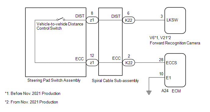
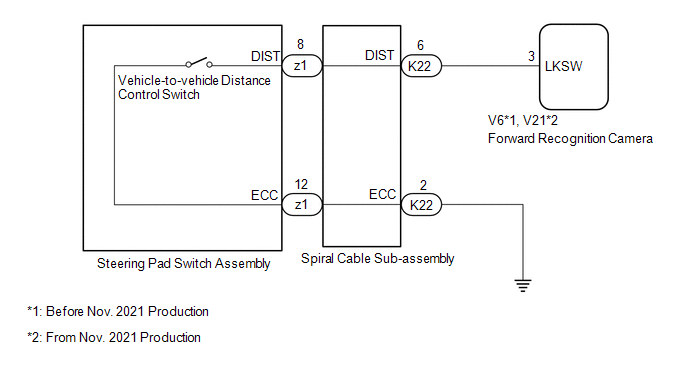
The vehicle-to-vehicle distance control switch is used to set the distance for vehicle-to-vehicle distance control mode. The vehicle-to-vehicle distance control switch is installed in the steering pad switch assembly. The vehicle-to-vehicle distance set value can be changed by operating the vehicle-to-vehicle distance control switch while the dynamic radar cruise control system is controlling vehicle speed in vehicle-to-vehicle distance control mode.
WIRING DIAGRAM
for A25A-FKS
for 2GR-FKS
CAUTION / NOTICE / HINT
NOTICE:
- The vehicle is equipped with a Supplemental Restraint System (SRS) which includes components such as airbags. Before servicing (including removal or installation of parts), be sure to read the precaution for Supplemental Restraint System.
Click here
.gif)
- When replacing the forward recognition camera, replace it with a new one. If a forward recognition camera which was installed to another vehicle is used, the information stored in the forward recognition camera will not match the information from the vehicle and a DTC may be stored.
- When the forward recognition camera is replaced with a new one or the windshield glass is replaced or removed/installed, make sure to read Before Starting Adjustment, then perform optical axis alignment for the forward recognition camera and clear the vehicle control history for each system.
HINT:
Forward recognition camera axis alignment can be performed by using either One Time Recognition, Sequential Recognition or Driving Adjustment.
One Time Recognition: Click here
Sequential Recognition: Click here
Driving Adjustment: Click here
- Before replacing the ECM, refer to Registration.
w/ Smart Key System: Click here
w/o Smart Key System: Click here
PROCEDURE
|
1. | READ VALUE USING TECHSTREAM (Radar Cruise2) |
(a) Read the Data List according to the display on the Techstream.
Powertrain > Radar Cruise2 > Data List|
Tester Display | Measurement Item |
Range | Normal Condition |
Diagnostic Note |
|---|---|---|---|---|
|
Vehicle-to-vehicle Distance Control Switch |
Vehicle-to-vehicle distance control switch signal |
ON or OFF | ON: Vehicle-to-vehicle distance control switch pushed OFF: Vehicle-to-vehicle distance control switch not pushed |
- |
|
Tester Display |
|---|
| Vehicle-to-vehicle Distance Control Switch |
OK:
The value of the Data List item changes according to the operation of the vehicle-to-vehicle distance control switch.
| OK | .gif) | PROCEED TO NEXT SUSPECTED AREA SHOWN IN PROBLEM SYMPTOMS TABLE |
|
.gif)
| 2. |
INSPECT STEERING PAD SWITCH ASSEMBLY |
Click here
| NG | | REPLACE STEERING PAD SWITCH ASSEMBLY |
|
| 3. |
INSPECT SPIRAL CABLE SUB-ASSEMBLY |
Click here
| NG | | REPLACE SPIRAL CABLE SUB-ASSEMBLY |
|
| 4. |
CHECK HARNESS AND CONNECTOR (SPIRAL CABLE SUB-ASSEMBLY - FORWARD RECOGNITION CAMERA, ECM AND BODY GROUND) |
(a) Disconnect the V6*1, V21*2 forward recognition camera connector.
- *1: Before Nov. 2021 Production
- *2: From Nov. 2021 Production
(b) Disconnect the A24 ECM connector (for A25A-FKS).
(c) Before Nov. 2021 Production:
(1) Measure the resistance according to the value(s) in the table below.
Standard Resistance:
for A25A-FKS:|
Tester Connection | Condition |
Specified Condition |
|---|---|---|
|
K22-6 (DIST) - V6-3 (LKSW) |
Always | Below 1 Ω |
|
K22-2 (ECC) - A24-28 (ECCS) |
Always | Below 1 Ω |
|
K22-6 (DIST) or V6-3 (LKSW) - Body ground |
Always | 10 kΩ or higher |
|
K22-2 (ECC) or A24-28 (ECCS) - Body ground |
Always | 10 kΩ or higher |
|
Tester Connection | Condition |
Specified Condition |
|---|---|---|
|
K22-6 (DIST) - V6-3 (LKSW) |
Always | Below 1 Ω |
|
K22-2 (ECC) - Body ground |
Always | Below 1 Ω |
|
K22-6 (DIST) or V6-3 (LKSW) - Body ground |
Always | 10 kΩ or higher |
(d) From Nov. 2021 Production:
(1) Measure the resistance according to the value(s) in the table below.
Standard Resistance:
for A25A-FKS:|
Tester Connection | Condition |
Specified Condition |
|---|---|---|
|
K22-6 (DIST) - V21-3 (LKSW) |
Always | Below 1 Ω |
|
K22-2 (ECC) - A24-28 (ECCS) |
Always | Below 1 Ω |
|
K22-6 (DIST) or V21-3 (LKSW) - Body ground |
Always | 10 kΩ or higher |
|
K22-2 (ECC) or A24-28 (ECCS) - Body ground |
Always | 10 kΩ or higher |
|
Tester Connection | Condition |
Specified Condition |
|---|---|---|
|
K22-6 (DIST) - V21-3 (LKSW) |
Always | Below 1 Ω |
|
K22-2 (ECC) - Body ground |
Always | Below 1 Ω |
|
K22-6 (DIST) or V21-3 (LKSW) - Body ground |
Always | 10 kΩ or higher |
|
Result | Proceed to |
|---|---|
|
OK (for A25A-FKS) | A |
|
OK (for 2GR-FKS) | B |
|
NG | C |
| B |
| REPLACE FORWARD RECOGNITION CAMERA |
| C |
| REPAIR OR REPLACE HARNESS OR CONNECTOR |
|
| 5. |
CHECK ECM (ECM TERMINALS) |
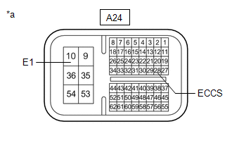
|
*a | Component without harness connected (ECM) |
(a) Disconnect the A24 ECM connector.
(b) Measure the resistance according to the value(s) in the table below.
Standard Resistance:
|
Tester Connection | Condition |
Specified Condition |
|---|---|---|
|
A24-28 (ECCS) - A24-10 (E1) |
Always | Below 1 Ω |
| OK | | REPLACE FORWARD RECOGNITION CAMERA |
| NG | | REPLACE ECM
|
READ NEXT:
 Cruise Main Indicator Light Circuit
DESCRIPTION When the dynamic radar cruise control system is turned on using the cruise control main switch, the cruise control indicator (vehicle-to-vehicle distance control mode) illuminates. The ECM
Cruise SET Indicator Light Circuit
DESCRIPTION The ECM illuminates the cruise SET indicator by sending request signals to the combination meter assembly via CAN communication. The cruise SET indicator illuminates when the dynamic radar
SEE MORE:
Freeze Frame Data
FREEZE FRAME DATA CHECK FREEZE FRAME DATA (a) Connect the Techstream to the DLC3.
(b) Turn the ignition switch to ON. (c) Turn the Techstream on.
(d) Enter the following menus: Body Electrical / Navigation System / Trouble Codes. Body Electrical > Navigation System > Trouble Codes
(e) Se
Brake Pressure Control Solenoid "C" Control Circuit Short to Battery (C14F112,...,C14FA49)
DESCRIPTION The ABS solenoid relay and reservoir cut solenoid valves are built into the brake actuator assembly.
When the brakes are operating, the reservoir cut solenoid valves supply brake fluid from the brake master cylinder reservoir assembly to the pump motor as necessary.
When this DTC is
