Toyota Camry (XV70): 2gr-fks Drive Belt
Components
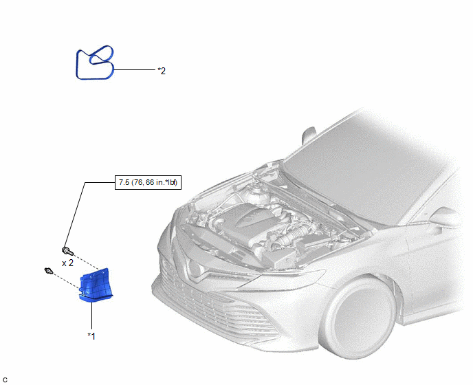
COMPONENTS
ILLUSTRATION
|
*1 | FRONT FENDER APRON SEAL RH |
*2 | V-RIBBED BELT |
Removal
REMOVAL
PROCEDURE
1. REMOVE FRONT WHEEL RH
Click here
.gif)
2. REMOVE FRONT FENDER APRON SEAL RH
Click here
3. REMOVE V-RIBBED BELT
|
(a) Release the V-ribbed belt tension by turning the V-ribbed belt tensioner assembly counterclockwise. |
|
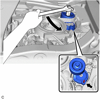
(b) Turn the V-ribbed belt tensioner assembly counterclockwise to align its holes, and then insert a 5 mm hexagon wrench to secure the V-ribbed belt tensioner assembly.
(c) Remove the V-ribbed belt from the V-ribbed belt tensioner assembly.
Installation
INSTALLATION
PROCEDURE
1. INSTALL V-RIBBED BELT
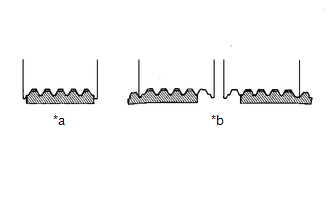
HINT:
When reusing the V-ribbed belt, check the ribs and back of the V-ribbed belt for wear and cracks. If wear or a crack that reaches the core (at more than 1 point) is found, replace the V-ribbed belt.
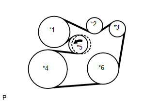
| (a) Install the V-ribbed belt. NOTICE:
|
|
(b) Turn the V-ribbed belt tensioner assembly counterclockwise and remove the 5 mm hexagon wrench.
| (c) After installing the V-ribbed belt, check that it fits properly in the ribbed grooves. Confirm that the V-ribbed belt has not slipped out of the grooves on the bottom of the pulley by hand. |
|
2. INSTALL FRONT FENDER APRON SEAL RH
Click here
.gif)
3. INSTALL FRONT WHEEL RH
Click here
READ NEXT:
 Components
COMPONENTS ILLUSTRATION
*1 FRONT WHEEL OPENING EXTENSION PAD LH
*2 FRONT WHEEL OPENING EXTENSION PAD RH
*3 NO. 1 ENGINE UNDER COVER
*4 REAR ENGINE UNDER COVER RH
Replacement
REPLACEMENT CAUTION / NOTICE / HINT
CAUTION:
Prolonged and repeated contact with engine oil will result in the removal of natural oils from the skin, leading to dryness, irritation and dermatiti
SEE MORE:
Key-off Operation Function Operates even if Operating Conditions are not Satisfied
DESCRIPTION The sliding roof ECU (sliding roof drive gear sub-assembly) operates its built-in motor according to the sliding roof switch (roof console box sub-assembly) operation. Using the sliding roof switch (roof console box sub-assembly), if the sliding roof can be operated normally when 45 seco
Cruise Control Input Processor (P160700)
MONITOR DESCRIPTION The ECM continuously monitors its main and sub CPUs. This self-check ensures that the ECM is functioning properly. If outputs from the CPUs are different and deviate from the standard, the ECM will illuminate the MIL and store the DTC immediately.
DTC No. Detection Item
