Toyota Camry (XV70): Installation
INSTALLATION
PROCEDURE
1. INSTALL ROOF ANTENNA ASSEMBLY (except Panoramic Moon Roof)
(a) When reusing the roof antenna assembly:
(1) Install a new seal.
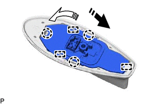
(b) Push the roof antenna assembly in the direction indicated by the arrow (1) shown in the illustration to engage the guide.
.png) |
Install in this Direction (1) |
.png) |
Install in this Direction (2) |
(c) Push the roof antenna assembly in the direction indicated by the arrow (2) shown in the illustration to engage the 2 guides and 3 claws and install the roof antenna assembly.
2. INSTALL ROOF ANTENNA ASSEMBLY WITH COVER (except Panoramic Moon Roof)
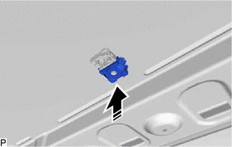
(a) Install a new washer and holder as shown in the illustration.
|
|
Install in this Direction |
(b) Install the roof antenna assembly with cover with the bolt.
Torque:
9.5 N
READ NEXT:
 Components
COMPONENTS ILLUSTRATION
*1 AUDIO AMPLIFIER COVER
*2 STEREO COMPONENT AMPLIFIER ASSEMBLY WITH BRACKET ILLUSTRATION
*1 NO. 1 AMPLIFIER BRACKET
*2 NO. 2 AMPLIFI
Removal
REMOVAL CAUTION / NOTICE / HINT
The necessary procedures (adjustment, calibration, initialization, or registration) that must be performed after parts are removed and installed, or replaced during s
SEE MORE:
Right Rear Wheel Speed Sensor Internal Electronic Failure (C051249)
DESCRIPTION When the system is starting up and the skid control ECU (brake actuator assembly) detects a speed sensor circuit malfunction via the speed sensor circuit self-diagnosis function, this DTC is stored.
DTC No. Detection Item
DTC Detection Condition Trouble Area
C05124
Doors
Unlocking and locking the doors from the outside
◆ Smart key system (if equipped)
Carry the electronic key to enable this function.
Grip the driver's door handle
to unlock the door. Holding
the driver's door handle for
approximately 2 seconds
unlocks all the doors. Grip
the front p
